Model predictive flux linkage control-based direct torque control method for switched reluctance motor

A switched reluctance motor, direct torque control technology, applied in the control of generators, control of electromechanical brakes, control of electromechanical transmissions, etc., can solve the problems of change lag, error, large torque ripple, etc., to reduce torque The effect of pulsation, elimination of first-order delay, and reduction of computational effort

Active Publication Date: 2019-02-15
DALIAN MARITIME UNIVERSITY
View PDF3 Cites 8 Cited by
  • Summary
  • Abstract
  • Description
  • Claims
  • Application Information

AI Technical Summary

Problems solved by technology

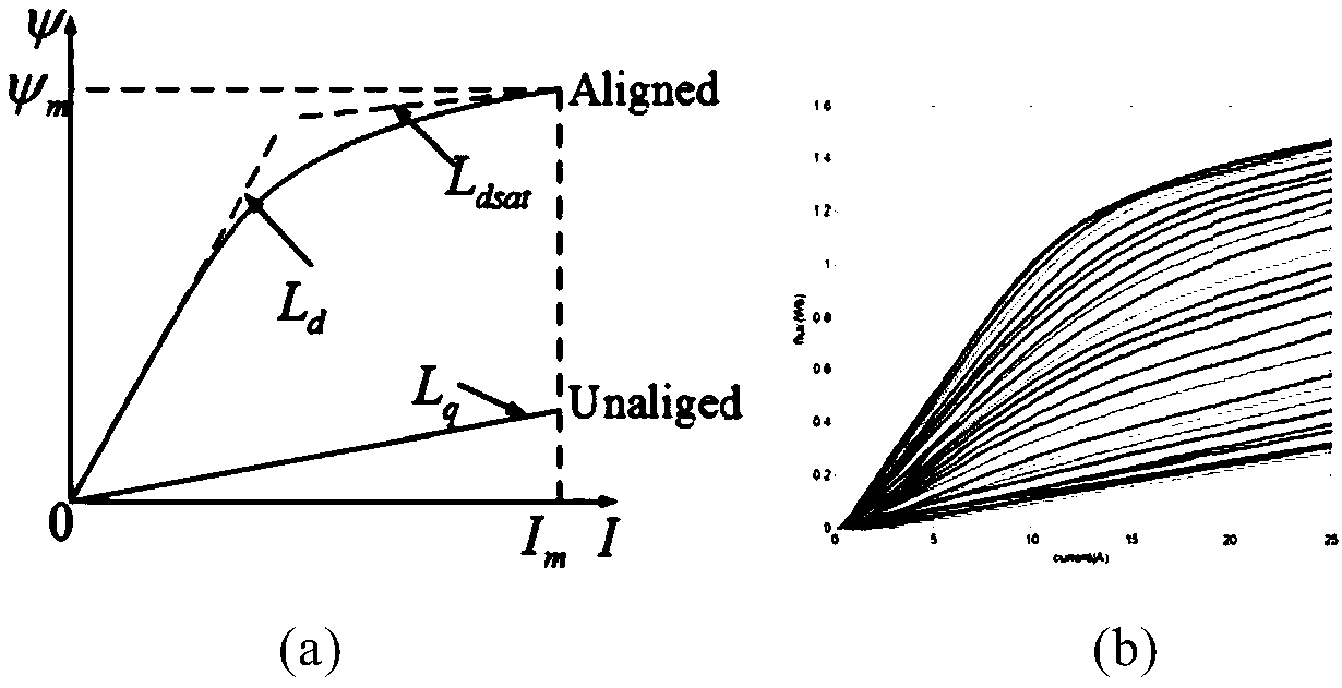
In DTC, the torque hysteresis loop and the flux linkage hysteresis loop simultaneously obtain the torque value and flux linkage value at the current moment, and compare them with the given torque flux linkage value to select the voltage vector to directly control the electromagnetic torque, although Torque is used as a direct control variable, but due to the nonlinear change between torque and flux linkage angle in SRM, the change of torque lags behind the change of flux linkage, and the real-time torque and flux linkage are compared and selected at the same time Voltage vectors inevitably cause errors
This error is especially obvious in the commutation area, which is also the reason why the traditional DTC has a large torque ripple in SRM control

Method used


Image

  • Model predictive flux linkage control-based direct torque control method for switched reluctance motor
  • Model predictive flux linkage control-based direct torque control method for switched reluctance motor
  • Model predictive flux linkage control-based direct torque control method for switched reluctance motor

Examples


Embodiment Construction

[0053] In order to enable those skilled in the art to better understand the solutions of the present invention, the following will clearly and completely describe the technical solutions in the embodiments of the present invention in conjunction with the drawings in the embodiments of the present invention. Obviously, the described embodiments are only It is an embodiment of a part of the present invention, but not all embodiments. Based on the embodiments of the present invention, all other embodiments obtained by persons of ordinary skill in the art without making creative efforts shall fall within the protection scope of the present invention.

[0054] It should be noted that the terms "first" and "second" in the description and claims of the present invention and the above drawings are used to distinguish similar objects, but not necessarily used to describe a specific sequence or sequence. It is to be understood that the data so used are interchangeable under appropriate ...


PUM


Abstract

The invention provides a model predictive flux linkage control-based direct torque control method for a switched reluctance motor. The direct torque control method at least comprises the following steps of measuring a current of a stator, a rotating speed of a rotor, a position of the rotor and a voltage of a direct-current link through sensors; calculating flux linkage of the stator and a torqueof a motor at a K moment; through a hysteresis ring controlled by the torque, comparing a torque value at the current K moment with a torque value set by a PI ring, and selecting out three to-be-selected voltage vectors; substituting the to-be-selected voltage vectors into a second-order Runge-Kutta method formula to predict the current of the stator at the K+1 moment; predicting a flux linkage value of the stator at the K+1 moment through the current of the stator at the K+1 moment; comparing a predicted flux linkage value psi k+1 of the stator at the K+1 moment with a given flux linkage value psi ref; selecting a Uk+1 voltage vector for minimizing an evaluation function through the evaluation function; sending a switch signal corresponding to the selected optimal voltage vector to a three-phase asymmetric bridge converter; and performing control on the switched reluctance motor.

Description

technical field [0001] The invention relates to the technical field of torque control of switched reluctance motors, in particular to a direct torque control method of switched reluctance motors based on model predictive flux linkage control. Background technique [0002] The switched reluctance motor (Switched Reluctance Motor, SRM or SR motor) was first proposed in the 1940s. Due to the technical conditions at that time, it was not well developed. However, after the 1960s, with the development of power electronic devices, SRM motors have also begun to be valued by the academic community. SRM has attracted widespread attention from academia and industry due to its advantages such as simple structure, low cost, high efficiency, and good speed regulation performance, and the number of papers and patents related to it has grown rapidly. Our country began to study SRM from about 1985. The products cover textiles, electric vehicles, home appliances, mining machinery, petroleu...

Claims


Application Information

Patent Timeline
Patent Type & Authority Applications(China)
IPC IPC(8): H02P21/12H02P21/14H02P25/098H02P27/12
CPCH02P21/12H02P21/141H02P27/12H02P25/098
Inventor 许爱德商超亿韩乐乐任萍张文
Owner DALIAN MARITIME UNIVERSITY
Why Eureka
Try Eureka