
Air box type pulse dedusting device

A technology of pulse dust collector and gas box, which is applied in gas treatment, chemical instruments and methods, and separation of dispersed particles. It is not easy to stick the bag and reduce the effect of static electricity

Inactive Publication Date: 2019-02-19
冯嘉豪
View PDF0 Cites 0 Cited by
  • Summary
  • Abstract
  • Description
  • Claims
  • Application Information

AI Technical Summary

Problems solved by technology

Especially the dust generated during the production of silicon materials, these dusts not only endanger the health of production workers, but also seriously pollute the environment and destroy the ecological balance. For this reason, the production lines of the above-mentioned industries must be equipped with dust removal and ash removal devices to eliminate the impact of dust on humans and the environment. pollution
[0003] In the existing air box pulse dust collector, because the compressed air directly enters the air storage tank, the water vapor in the air is compressed into water particles. When it enters the pulse valve and is sprayed out, the water particles directly adhere to the cloth bag of the dust collector to form a cloth bag. Moisture, mixed with dust, adheres to the bag wall, reduces the air permeability of the bag, causes the phenomenon of sticking the bag, and hardens the bag after long-term use; in addition, most of the bags used in the existing dust collectors are ordinary fiber bags. In the case of pasting bags, two pieces of cloth are squeezed and rubbed against each other, which is prone to generate static electricity, which will cause the dust collector to explode. Therefore, people continue to improve the material of the cloth bag to reduce the generation of static electricity, but they still ignore the pasting of the cloth bag. The problem is that the dust removal is not stable enough after the dust collector is used for a long time
However, with the rapid development of the social economy, the existing dust collectors no longer use several cloth bags for dust removal, and in order to improve the dust removal efficiency, several cloth bags are installed in the box, but the bag is loose, and it is more likely to appear during use. Paste bags, and there will be paste bags between adjacent cloth bags, so there are problems of easy paste bags and poor dust removal effect; in addition, the existing cloth bags all use ordinary fiber bags, and the existing ordinary fiber bags are in use When it is used, it is prone to stiffness, and the dust cannot be removed to the maximum extent when the pulse is blown. In addition, the ordinary fiber bag is not elastic, which will reduce the dust removal effect when used, and the ordinary fiber bag has poor performance and short service life. The problem

Method used


Image

  • Air box type pulse dedusting device
  • Air box type pulse dedusting device
  • Air box type pulse dedusting device

Examples


Embodiment 1

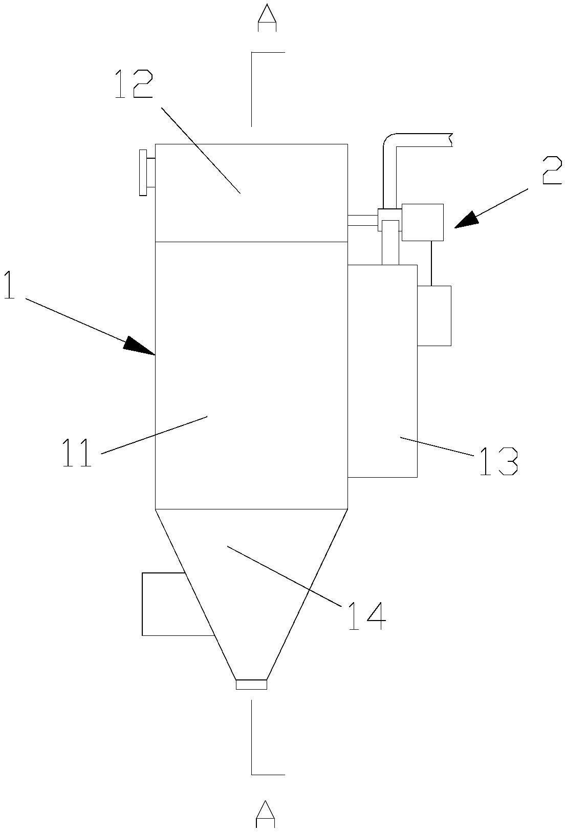
[0021] A gas box type pulse dust collector, such as figure 1 As shown, it includes a dust-collecting gas box 1, and a pulse device 2 arranged on one side of the dust-collecting gas box 1 and used in conjunction with the dust-collecting gas box 1;

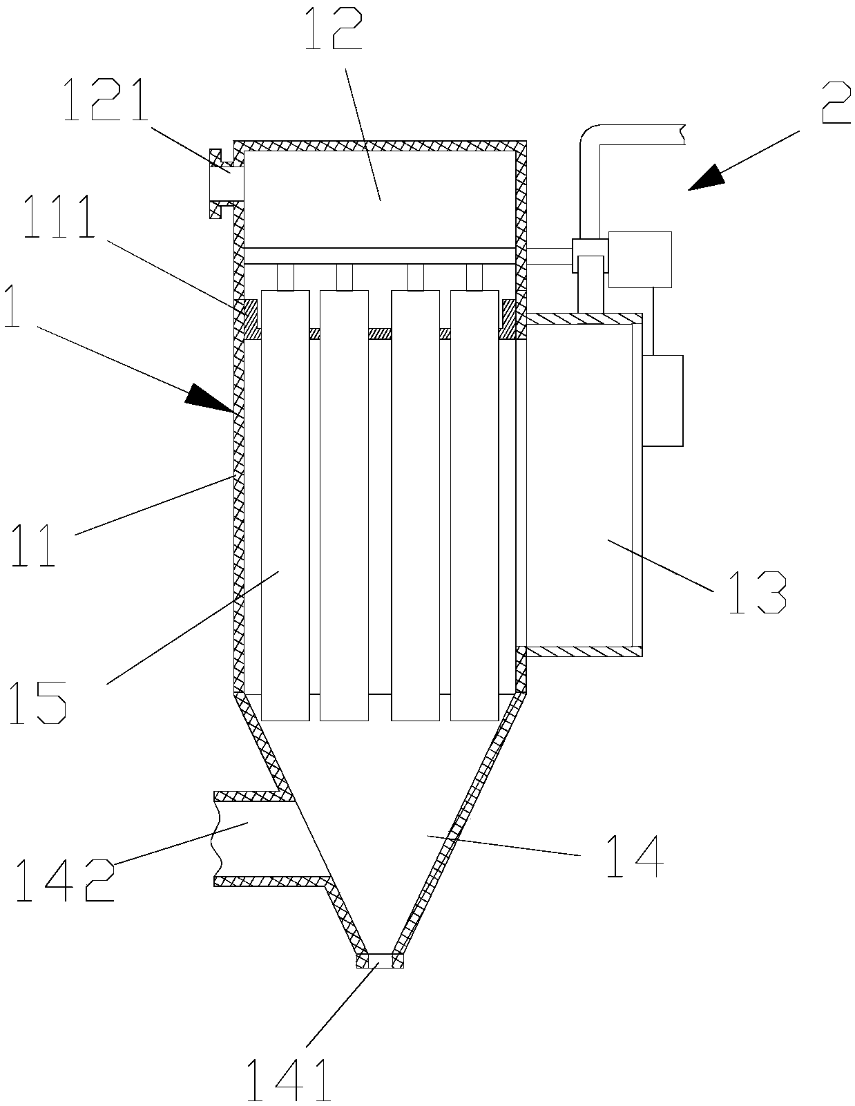
[0022] Such as figure 2 As shown, the dust-collecting air box 1 includes a main box body 11 with an accommodating space inside, and an air outlet cavity 12 arranged above the main box body 11 and fixed to the main box body 11, and arranged on the main box body The inspection door 13 on the side of 11 and communicated with the main box body 11, the dust hopper 14 arranged under the main box body 11, and the bag tube 15 for dust collection arranged in the main box body 11; The upper end of the inside of the main box 11 is provided with a fixing plate 111, and the fixing plate 111 and the main box 11 are fixed by screws, and the bag tube 15 is fixed by the fixing plate 111, so that the bag tube 15 is suspended by the fixing plate 111...

Embodiment 2

[0034] A gas box type pulse dust collector, such as figure 1 As shown, it includes a dust-collecting gas box 1, and a pulse device 2 arranged on one side of the dust-collecting gas box 1 and used in conjunction with the dust-collecting gas box 1;

[0035] Such as figure 2 As shown, the dust-collecting air box 1 includes a main box body 11 with an accommodating space inside, and an air outlet cavity 12 arranged above the main box body 11 and fixed to the main box body 11, and arranged on the main box body The inspection door 13 on the side of 11 and communicated with the main box body 11, the dust hopper 14 arranged under the main box body 11, and the bag tube 15 for dust collection arranged in the main box body 11; The upper end of the inside of the main box 11 is provided with a fixing plate 111, and the fixing plate 111 and the main box 11 are fixed by screws, and the bag tube 15 is fixed by the fixing plate 111, so that the bag tube 15 is suspended by the fixing plate 111...

Embodiment 3

[0047] A gas box type pulse dust collector, such as figure 1 As shown, it includes a dust-collecting gas box 1, and a pulse device 2 arranged on one side of the dust-collecting gas box 1 and used in conjunction with the dust-collecting gas box 1;

[0048] Such as figure 2 As shown, the dust-collecting air box 1 includes a main box body 11 with an accommodating space inside, and an air outlet cavity 12 arranged above the main box body 11 and fixed to the main box body 11, and arranged on the main box body The inspection door 13 on the side of 11 and communicated with the main box body 11, the dust hopper 14 arranged under the main box body 11, and the bag tube 15 for dust collection arranged in the main box body 11; The upper end of the inside of the main box 11 is provided with a fixing plate 111, and the fixing plate 111 and the main box 11 are fixed by screws, and the bag tube 15 is fixed by the fixing plate 111, so that the bag tube 15 is suspended by the fixing plate 111...


PUM

PropertyMeasurementUnit
melting pointaaaaaaaaaa

Abstract

The invention discloses an air box type pulse dedusting device. The device includes a dust collecting air box and a pulse apparatus arranged on one side of the dust collecting air box; the dust collecting air box comprises a main box body internally provided with a containing space, a gas outlet chamber formed above the main box body, a checking door arranged on one side of the main box body, a dust outlet hopper arranged below the main box body and a bag drum which is arranged in the main box body and used for collecting dust. The bag drum includes a cylindrical support framework and a clothbag arranged on the support framework. The bag drum in the device supports the cloth bag through the support framework to prevent the cloth bag from being bonded during use; meanwhile, the cloth bag is also tightened by the support framework and thus can vibrate during pulse blowing for dedusting, and therefore the dust is more likely to detach from the cloth bag, so that the effects of maintaining stability during dedusting and preventing the bag from being burnt are achieved. Meanwhile, a novel environment-friendly material is adopted for processing and preparing the cloth bag, not only is the cost reduced, but also the generation possibility of static electricity is lowered, and improvement of the safety performance of the device is facilitated.

Description

technical field [0001] The invention relates to an air box type pulse dust collector. Background technique [0002] Nowadays, in the production process of grain, iron and steel, non-ferrous metals, minerals, chemicals and building materials, a large amount of various dusts will be generated. Especially the dust generated during the production of silicon materials, which not only endangers the health of production workers, but also seriously pollutes the environment and destroys the ecological balance. Therefore, the production lines of the above-mentioned industries must be equipped with dust removal and ash removal devices to eliminate the impact of dust on humans and the environment. pollution. [0003] In the existing air box pulse dust collector, because the compressed air directly enters the air storage tank, the water vapor in the air is compressed into water particles. When it enters the pulse valve and is sprayed out, the water particles directly adhere to the cloth...

Claims


Application Information

Patent Timeline
Patent Type & Authority Applications(China)
IPC IPC(8): B01D46/04B01D46/06B01D46/50B01D46/02
CPCB01D46/04B01D46/023B01D46/06B01D46/50B01D2258/02B01D2258/025
Inventor 不公告发明人
Owner 冯嘉豪
Learn More