Eureka AIR delivers breakthrough ideas for toughest innovation challenges, trusted by R&D personnel around the world.

Air purifier

An air purifier and vibration generator technology, applied in the field of air purification, can solve the problems of affecting the filtration effect, frequent replacement of the filter element, short filter life, etc., and achieve the effect of reducing human intervention and improving the collection and storage effect.

Pending Publication Date: 2019-02-19
XIAMEN ZHONGCHUANG ENVIRONMENTAL TECH CO LTD
View PDF0 Cites 4 Cited by
  • Summary
  • Abstract
  • Description
  • Claims
  • Application Information

AI Technical Summary

Problems solved by technology

Since the pollutants are directly accumulated on the outer surface of the filter element when this type of purifier is working, the accumulated particle dust will seriously affect the filtering effect in the later stage, and it is easy to become a place for bacteria to multiply and form secondary pollution.
In addition, the phenomenon of dust and haze in the regional air in my country is very serious, resulting in the short life of the dust-holding filter element, and the technical method of quantitative estimation of the filter element life is immature, and the measurement results deviate greatly from the actual situation.
Such filter elements generally cannot be completely and thoroughly cleaned, resulting in frequent replacement of filter elements, accompanied by troublesome disassembly and installation
Although the electrostatic precipitator can realize the reuse of its metal filter plate, it cannot effectively control the generation of ozone, and it also needs to be disassembled and cleaned irregularly
The disadvantages of air purifiers using plasma and negative ion technology are that the amount of air to be purified is small, the energy consumption is large, and there are strict requirements on the area of ​​use.

Method used


Image

  • Air purifier
  • Air purifier
  • Air purifier

Examples


Embodiment Construction

[0025] In order to further explain the technical solution of the present invention, the present invention will be described in detail below through specific examples.

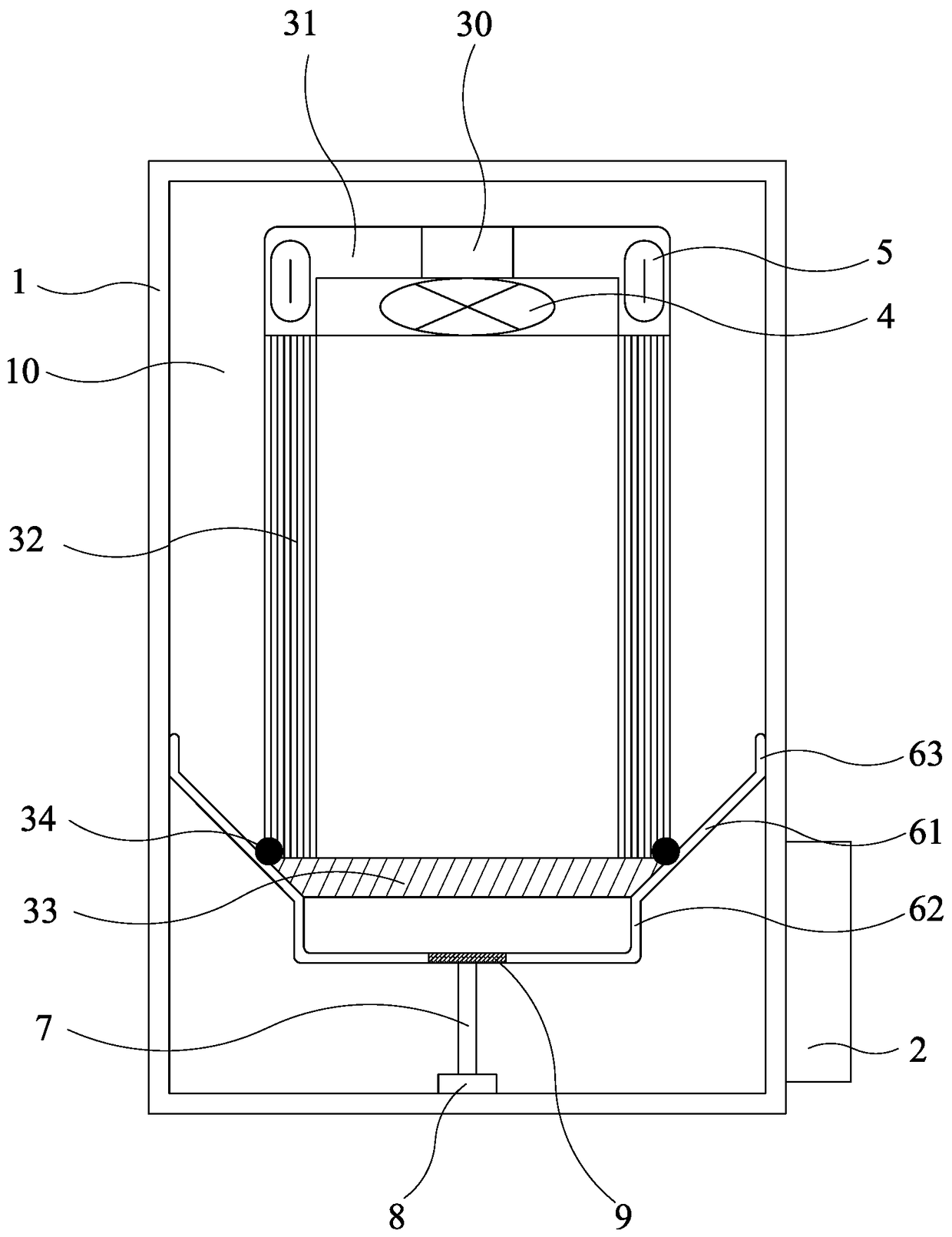
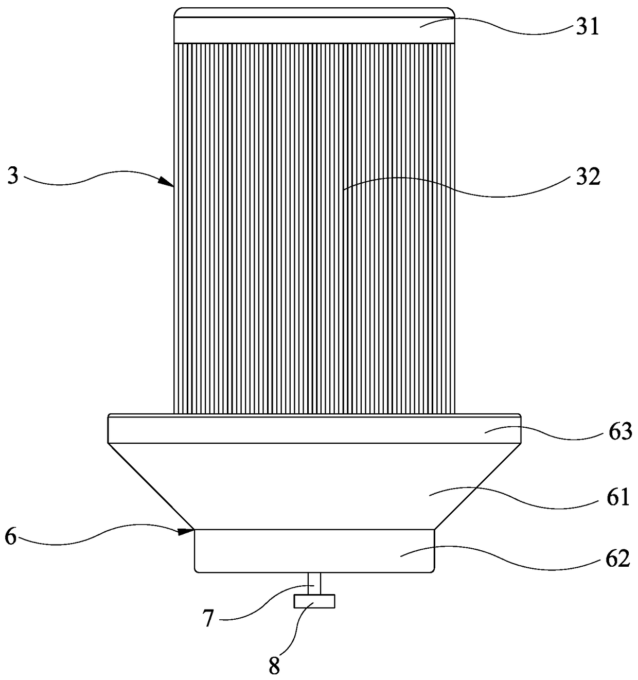
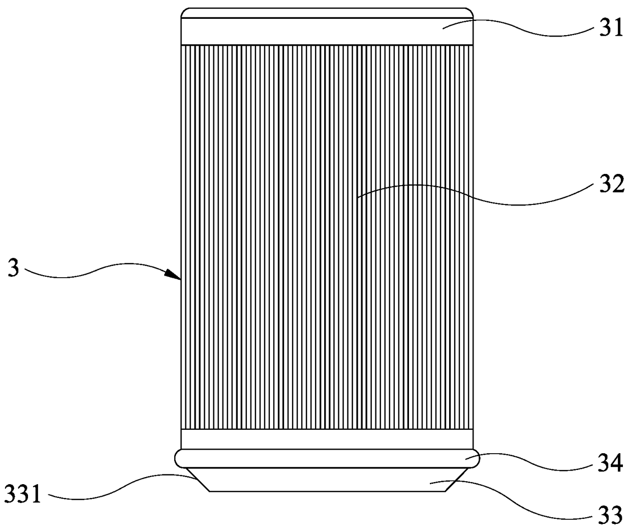
[0026] Such as figure 1 and figure 2 As shown, an air cleaner includes a casing 1, a filter assembly, an ash collection assembly and a control panel 2, wherein the filter assembly and the ash collection assembly are installed inside the casing 1, and the control panel 2 is installed on the casing 1.

[0027] The casing 1 is hollowed out so that air can enter and exit the casing 1, and an accommodating space 10 for installing the filter assembly and the ash collection assembly is provided inside.

[0028] The filter assembly includes a filter cartridge 3 , a vortex fan 4 and a vibration generator 5 . The upper end of the filter cartridge 3 is provided with an air outlet 30, the diameter of the filter cartridge 3 ranges from 130-400mm, and the height ranges from 200-550mm. The vortex fan 4 is installed on the...


PUM

PropertyMeasurementUnit
diameteraaaaaaaaaa
heightaaaaaaaaaa

Abstract

The invention discloses an air purifier. The air purifier comprises a housing, a filtering assembly, a dust collecting assembly and a control circuit board, the housing is of a hollow-out structure, the filtering assembly and the dust collecting assembly are installed in the housing, the control circuit board is fixed on the housing, the filter assembly comprises a filter tube, a turbine fan and avibration generator, the filter tube is provided with an air outlet, the turbine fan is installed on the filter tube and is electrically connected with the control circuit board, the vibration generator is installed on the filter tube and is electrically connected with the control circuit board, and the dust collecting assembly comprises a dust collecting box which is installed below the filter tube. By arranging the vibration generation on the filter tube, dust particles adhering to the outer surface of the filter tube can be automatically cleaned by the air purifier, dust particles can be collected by the dust collecting box under the action of gravitational force to prevent the problems of the accumulation of dust particles and secondary pollution, so that the service life of the air purifier is prolonged, and the trouble of frequent replacement and cleaning of filter core is prevented. The use of the air purifier is not restricted by air environment, so that the air purifier has more marketing value.

Description

technical field [0001] The invention relates to the technical field of air purification, in particular to an air purifier. Background technique [0002] At present, there are many types of air purifiers on the market, and the research and development of traditional air purifiers follow the idea of ​​increasing the dust holding capacity of the filter element as much as possible. Because pollutants are directly accumulated on the outer surface of the filter element when this type of purifier is working, the accumulated particle dust will seriously affect the filtering effect in the later stage, and it is easy to become a place for bacteria to multiply and form secondary pollution. In addition, the dust and smog in the regional air in my country are very serious, resulting in the short life of the dust-holding filter element, and the technical method of quantitative estimation of the filter element life is immature, and the measurement results deviate greatly from the actual si...

Claims


Application Information

Patent Timeline
Patent Type & Authority Applications(China)
IPC IPC(8): B01D46/42B01D46/24B01D46/48
CPCB01D46/2411B01D46/48B01D46/76
Inventor 王巍蔡伟龙林鸿剑牛强李彪郑锦森游丽容邱薰艺
Owner XIAMEN ZHONGCHUANG ENVIRONMENTAL TECH CO LTD
Why Eureka
Eureka Blog
Learn More