Automatic transferring and punching mechanism for aluminum profile

An aluminum profile and push mechanism technology, applied in perforating tools, metal processing equipment, manufacturing tools, etc., can solve the problems of aluminum profile skew, punching, difficult aluminum profiles, etc., to achieve reasonable structural design, improve automation, and Avoid offset skew effects

Pending Publication Date: 2019-02-19
ZHEJIANG ZHUOYI ALUMINUM
View PDF0 Cites 6 Cited by
  • Summary
  • Abstract
  • Description
  • Claims
  • Application Information

AI Technical Summary

Problems solved by technology

In order to facilitate fixed installation, during the production process of aluminum profiles, the aluminum profiles need to be punched according to the needs of the installation. The existing aluminum profile punching device has a complex structure and troublesome operation, and it is difficult to punch aluminum profiles quickly and efficiently. In the process of punching the aluminum profile, the existing punching device is difficult to transfer the aluminum profile intermittently. Generally, it can only measure the distance of the aluminum one by one and then punch the hole, which makes it difficult to realize the aluminum profile during the punching process. Continuous drilling process, the drilling efficiency is low and the drilling quality is poor, the labor intensity of the workers is high, and the existing aluminum profiles are difficult to be fully and smoothly pressed and fixed during the drilling process, resulting in aluminum The profile is skewed during the drilling process, which affects the high-quality drilling of the aluminum profile, and it is difficult to meet the needs of production and use.

Method used


Image

  • Automatic transferring and punching mechanism for aluminum profile
  • Automatic transferring and punching mechanism for aluminum profile
  • Automatic transferring and punching mechanism for aluminum profile

Examples


Embodiment Construction

[0016] In order to further describe the present invention, a specific implementation of an aluminum profile automatic feeding and punching mechanism will be further described below in conjunction with the accompanying drawings. The following examples are explanations of the present invention and the present invention is not limited to the following examples.

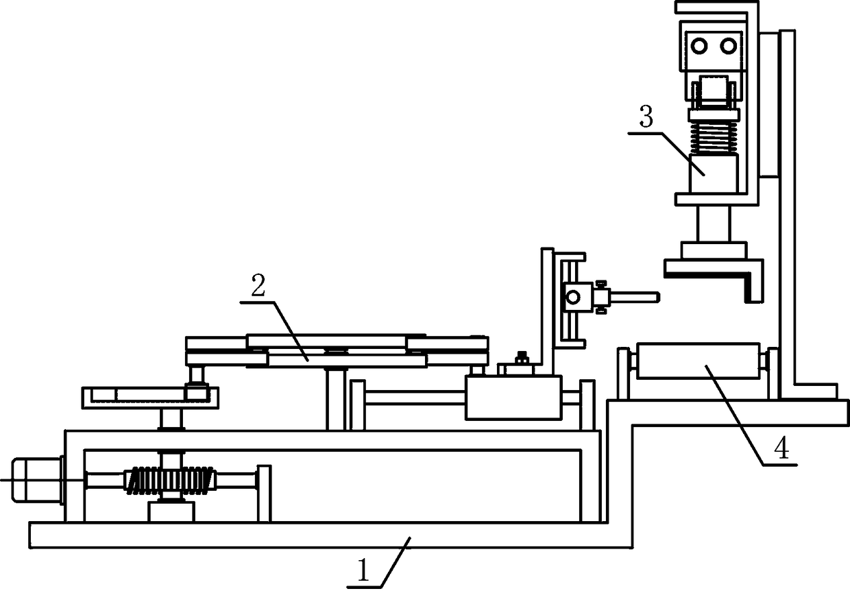
[0017] Such as figure 1 As shown, an aluminum profile automatic transfer punching mechanism of the present invention includes a fixed base 1, a profile punching mechanism 2, a profile pressing mechanism 3 and a profile pushing mechanism 4, and the profile punching mechanism 2 is horizontally arranged above the fixed base 1. On the side, the profile pressing mechanism 3 and the profile pushing mechanism 4 are fixedly arranged on the fixed base 1 above one side of the profile punching mechanism 2 along the horizontal direction, and the profile pressing mechanism 3 is vertically adjacently arranged on the profile punching me...


PUM


Abstract

The invention discloses an automatic transferring and punching mechanism for an aluminum profile, and belongs to the field of profile processing machines. A profile compressing mechanism and a profilepushing mechanism are sequentially and fixedly arranged on a fixed base above one side of a profile punching mechanism in the horizontal direction. The middle of the lower side of one end of a rotarycam is fixedly connected with the upper end of a cam rotary shaft, and a translation connecting plate is slidingly arranged on a translation guide rod in the horizontal direction. An adjusting connecting plate is vertically arranged on the upper side of the translation connecting plate, and a punching round rod is horizontally arranged on one side of an adjusting guide plate. Lifting pressing plates are vertically arranged on the two sides of the lower portion of a compressing support correspondingly. A plurality of translation guide rolls are sequentially arranged on a discharging support onthe lower side of a profile compressing plate in the horizontal direction. A pushing guide plate is slidingly arranged on a pushing guide rod in the horizontal direction. The automatic transferring and punching mechanism is reasonable in structural design, an aluminum profile is subjected to translation and pushing intermittently, the aluminum profile can be continuously punched, the automation degree of aluminum profile punching is improved, and the needs of processing use are met.

Description

technical field [0001] The invention belongs to the field of profile processing machinery and equipment, and in particular relates to an aluminum profile automatic transfer punching mechanism, which is mainly used in the continuous punching process of aluminum profiles. Background technique [0002] Profile refers to the straight strip with certain end face shape and size after plastic processing, and occupies a very important position in the rolling production of profile. The profile is an object with a certain geometric shape made of iron or steel and other metal materials with certain strength and toughness through rolling, extrusion and casting. Mechanical and physical properties. Profiles can be used alone or further processed into other manufactured products. They are often used in building structures and manufacturing installations. During the processing and manufacturing of profiles, mechanical engineers can choose the specific shape, material, and heat treatment sta...

Claims


Application Information

Patent Timeline
Patent Type & Authority Applications(China)
IPC IPC(8): B21D28/24B21D28/34B21D43/00B21D43/02
CPCB21D28/243B21D28/34B21D43/003B21D43/02
Inventor 聂姗姗张成沈建山
Owner ZHEJIANG ZHUOYI ALUMINUM
Why Eureka
Try Eureka