Concrete pouring guide mechanism

A technology of concrete and material guide frame, which is applied in the direction of building structure, building material processing, construction, etc., and can solve problems that affect concrete pouring processing, cannot meet the needs of building construction, and it is difficult to ensure that the concrete is scattered and distributed.

Pending Publication Date: 2022-07-08
桐乡市钟大建材有限公司
View PDF0 Cites 0 Cited by
  • Summary
  • Abstract
  • Description
  • Claims
  • Application Information

AI Technical Summary

Problems solved by technology

In the process of concrete pouring, the concrete delivery pump uses the delivery pipe to efficiently transport the concrete to the designated location, and the distribution pipe connected to the delivery pipe guides the concrete to the position to be poured. The efficiency and quality of concrete pouring requires that the concrete conveyed by the concrete pump be distributed evenly and synchronously during the blanking process. Therefore, during the concrete pouring process, it is necessary to move the distributing pipes to the required pouring positions in sequence in a smooth and orderly manner. The translation and swing of the pipe is usually manually pushed and pulled by construction workers. Therefore, in the process of conveying and dropping concrete by the distribution pipe, construction workers are required to continuously move and push and pull the distribution pipe. The labor intensity of the workers is high, and it is difficult to ensure that the concrete is smoothly Uniform distribution of materials affects the normal and efficient pouring process of concrete, which cannot meet the needs of building construction.

Method used


Image

  • Concrete pouring guide mechanism
  • Concrete pouring guide mechanism
  • Concrete pouring guide mechanism

Examples


Embodiment Construction

[0020]In order to further describe the present invention, a specific embodiment of a concrete pouring guide mechanism is further described below with reference to the accompanying drawings. The following examples are for explaining the present invention and the present invention is not limited to the following examples.

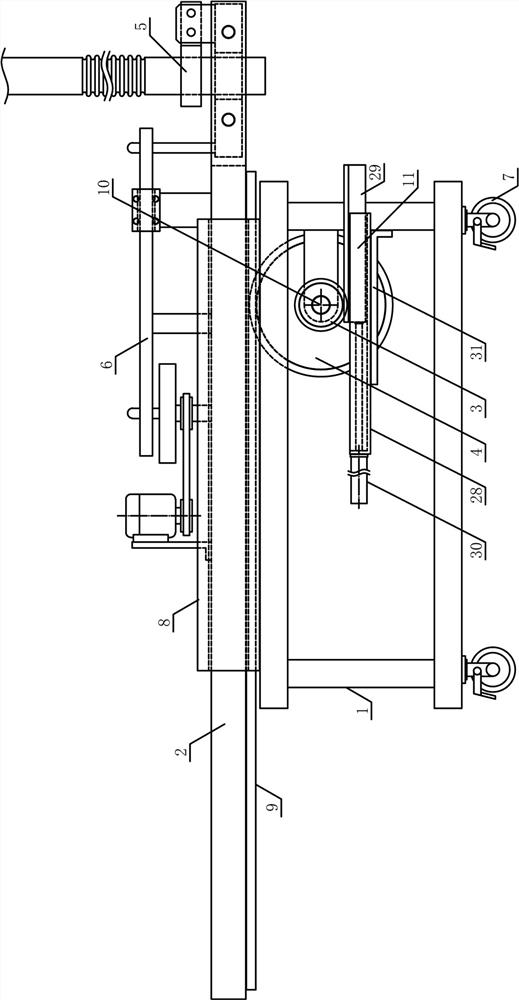
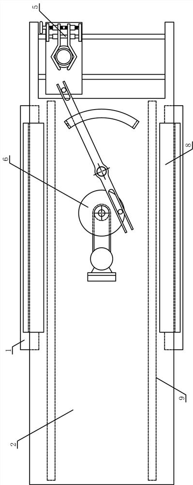
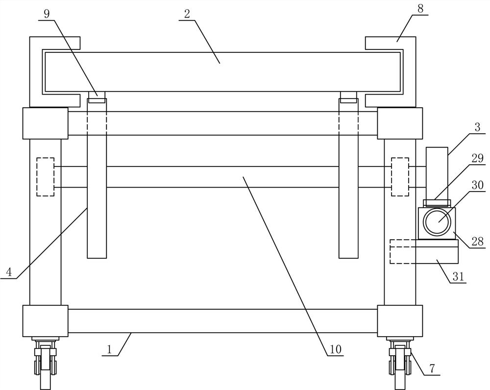
[0021] like figure 1 , figure 2 and image 3 As shown, a concrete pouring guide mechanism of the present invention includes a pouring guide frame 1, a reciprocating flat guide plate 2, a guide main gear 3, a guide auxiliary gear 4, a reciprocating distribution mechanism 5 and a distribution drive mechanism 6. The lower side of the frame 1 is evenly provided with a plurality of universal wheels 7 with brakes, the upper and lower sides of the pouring guide frame 1 are respectively horizontally fixed with reciprocating flat guide rails 8, and the reciprocating flat guide plate 2 is arranged on the upper side of the pouring guide frame 1. The guide plate 2 is ...


PUM


Abstract

The invention discloses a concrete pouring material guiding mechanism, and belongs to the field of building construction mechanical equipment. A plurality of universal wheels with brakes are evenly arranged on the lower side of a pouring material guide frame, a reciprocating flat guide plate is horizontally arranged on a reciprocating flat guide rail in a sliding mode, material guide auxiliary gears are arranged on the two sides of a material guide driving rotating shaft below the reciprocating flat guide plate respectively, and the material guide auxiliary gears are connected with a translation rack below the reciprocating flat guide plate in a meshed mode. A material guiding main gear is vertically and fixedly arranged at the end of one side of the material pouring driving rotating shaft, a translation driving mechanism is arranged on the pouring material guiding frame on the side adjacent to the material guiding main gear, the reciprocating material distributing mechanism is horizontally arranged at the end of the reciprocating flat guide plate, and the material distributing driving mechanism is adjacent to the reciprocating flat guide plate on the side adjacent to the reciprocating material distributing mechanism. The concrete pouring device is reasonable in structural design, the concrete guide pipe can perform efficient and stable translational motion in the pouring process, efficient and uniform falling and pouring of concrete are achieved, the automation degree of concrete pouring construction is improved, and the use requirements of buildings are met.

Description

technical field [0001] The invention belongs to the field of construction machinery and equipment, in particular to a concrete pouring guide mechanism. Background technique [0002] Concrete is the main civil engineering material. It is an artificial building material made of cementitious materials, granular aggregates, water, admixtures and admixtures in a certain proportion, uniformly stirred, compacted and cured. . Concrete pouring refers to the process of pouring concrete into the mold until it solidifies. In civil construction engineering, materials such as concrete are put into the mold to form a predetermined shape. Concrete pouring mainly includes concrete column pouring, concrete beam slab pouring and concrete stair pouring. The concrete is usually poured by a concrete delivery pump to deliver the concrete to the designated position. The concrete delivery pump is a machine that continuously transports concrete along the pipeline by using pressure. Pipes and placin...

Claims


Application Information

Patent Timeline
IPC IPC(8): E04G21/04E04G21/02
CPCE04G21/0436E04G21/02Y02E10/20
Inventor 张骏杰姚晓光
Owner 桐乡市钟大建材有限公司
Why Eureka
Try Eureka