Manual reinforcing steel bar bending tool and operation method thereof

A steel bar bending and tool technology, which is applied in the field of manual steel bar bending tools, can solve the problems of heavy workload, large space occupation, and high cost, and achieve the effects of convenient operation, simple structure, and improved bending efficiency and bending accuracy

Pending Publication Date: 2019-02-19
NORTH CHINA UNIVERSITY OF SCIENCE AND TECHNOLOGY
View PDF0 Cites 4 Cited by
  • Summary
  • Abstract
  • Description
  • Claims
  • Application Information

AI Technical Summary

Problems solved by technology

With the extensive use of reinforced concrete, the use of bending at various angles of steel bars is also increasing. In the past, manual bending was used, but due to the large workload and large errors in bending angles, hydraulic steel bending machines and digital bending machines appeared one after another. Although these bending machines have added the functions of straightening, bending and automatic cutting, the simple bending performance is good, but the functions of multiple angles and one-time forming in a single piece cannot be realized, and it takes up The space is large and the purchase cost is high. It is difficult to place reinforced concrete scientific research laboratories and small construction sites with small spaces. In addition, the amount of steel bars used in laboratories and small buildings is small, and the cost of using hydraulic steel bending machines and digital steel bending machines is high. , the traditional manual steel bar bending tools have low efficiency and large steel bar processing errors, which are difficult to meet the requirements of scientific research experiments

Method used


Image

  • Manual reinforcing steel bar bending tool and operation method thereof
  • Manual reinforcing steel bar bending tool and operation method thereof
  • Manual reinforcing steel bar bending tool and operation method thereof

Examples


Embodiment Construction

[0102] The present invention is described in detail below with reference to accompanying drawing and embodiment:

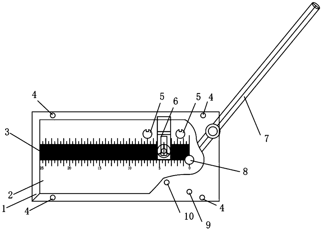
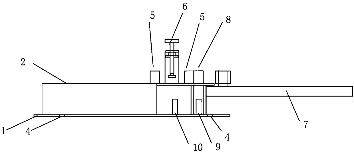
[0103] attached Figure 1-12 It can be seen that a manual steel bar bending tool,

[0104] Including: including console base 1 and console top 2;

[0105] The operating table 2 is arranged above the operating table base 1;

[0106] The operating table 2 is connected to the operating table base 1 through a connecting plate arranged in the vertical direction, and is characterized in that:

[0107] The operating table 2 is provided with a positioning column 5, a compactor 6 and a bending center positioning column 8;

[0108] A wrench 7 is arranged between the console base 1 and the console surface 2 .

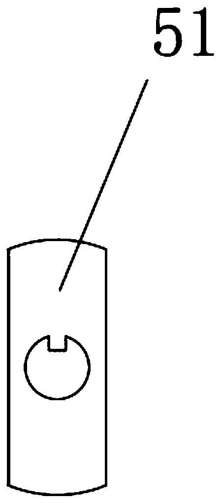
[0109] The positioning column 5 is provided with a groove;

[0110] A positioning sleeve 51 is set on the outside of the positioning column 5;

[0111] The positioning sleeve 51 is provided with a connecting hole;

[0112] A protrusion is arranged in the connec...


PUM

PropertyMeasurementUnit
diameteraaaaaaaaaa

Abstract

The invention relates to a manual reinforcing steel bar bending tool and an operation method thereof. The manual reinforcing steel bar bending tool comprises an operating floor base and an operation table, wherein the operating table is arranged above the operating floor base and is connected with the operating floor base through a connecting plate arranged in the vertical direction. The manual reinforcing steel bar bending tool is characterized in that a positioning column, a presser and a bending circle center positioning column are arranged on the operation table; and a spanner is arrangedbetween the operating floor base and the operation table. The manual reinforcing steel bar bending tool provided by the invention is simple in structure and convenient to operate; the reinforcing steel bar bending efficiency and the reinforcing steel bar bending accuracy are improved; the presser is arranged on the reinforcing steel bar operation table, and the reinforcing steel bar is fixed whenbeing bent, so that the precision of the length of a hook is ensured; and the presser can move in a long hole at a flat plate suspension section according to the position of the reinforcing steel bar,and a pressing plate can freely rotate along the axis of a screw rod and cannot rotate on the surface of the reinforcing steel bar along with the rotating of a hand wheel, so that the influence of pressing on the physical property and the mechanical property of the reinforcing steel bar is reduced.

Description

technical field [0001] The invention relates to the field of construction machinery and equipment, in particular to a manual steel bar bending tool. Background technique [0002] Reinforcement refers to steel for reinforced concrete and prestressed reinforced concrete, which is circular in cross-section and sometimes square with rounded corners. With the extensive use of reinforced concrete, the use of bending at various angles of steel bars is also increasing. In the past, manual bending was used, but due to the large workload and large errors in bending angles, hydraulic steel bending machines and digital bending machines appeared one after another. Although these bending machines have added the functions of straightening, bending and automatic cutting, the simple bending performance is good, but the functions of multiple angles and one-time forming in a single piece cannot be realized, and it takes up The space is large and the purchase cost is high. It is difficult to p...

Claims


Application Information

Patent Timeline
Patent Type & Authority Applications(China)
IPC IPC(8): B21F1/00
CPCB21F1/00B21F1/002
Inventor 刘益良苏幼坡陈海彬赵江山王硕韩流涛武立伟田杰芳马丹祥
Owner NORTH CHINA UNIVERSITY OF SCIENCE AND TECHNOLOGY
Why Eureka
Try Eureka