Broach positioning clamping device

A technology for positioning and clamping and clamping components, which is applied in the directions of broaching device, accessories of broaching device, broaching machine, etc., which can solve the problems of high cost and complicated equipment structure, and achieve the advantages of simple structure, convenient operation and simplified structure. Effect

Pending Publication Date: 2019-02-19
WUHU JINYI MACHINERY
View PDF1 Cites 3 Cited by
  • Summary
  • Abstract
  • Description
  • Claims
  • Application Information

AI Technical Summary

Problems solved by technology

However, it can be seen from its instruction manual that the clamping cylinder is used in the scheme to

Method used


Image

  • Broach positioning clamping device
  • Broach positioning clamping device
  • Broach positioning clamping device

Examples


Embodiment 1

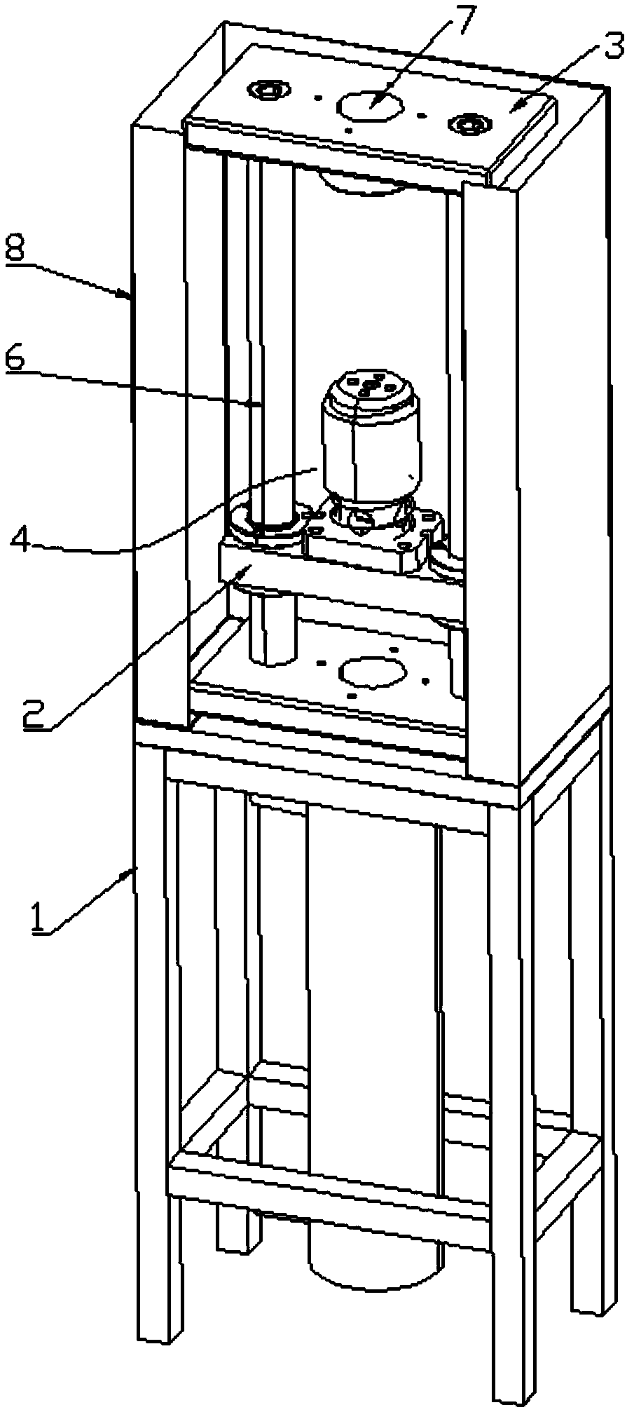
[0023] Such as Figure 1 to Figure 5 As shown, a broach positioning and clamping device includes a workbench 1, a support platform 2, a guide seat 3 and a clamping assembly 4. The top of the workbench 1 is provided with two guide columns 6, and the support platform 2 Installed on the guide post 6 and at a distance from the top surface of the workbench 1, the guide seat 3 is installed on the top of the guide post and the guide seat 3 is provided with a guide hole 7;

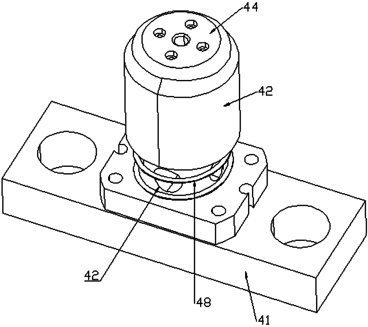
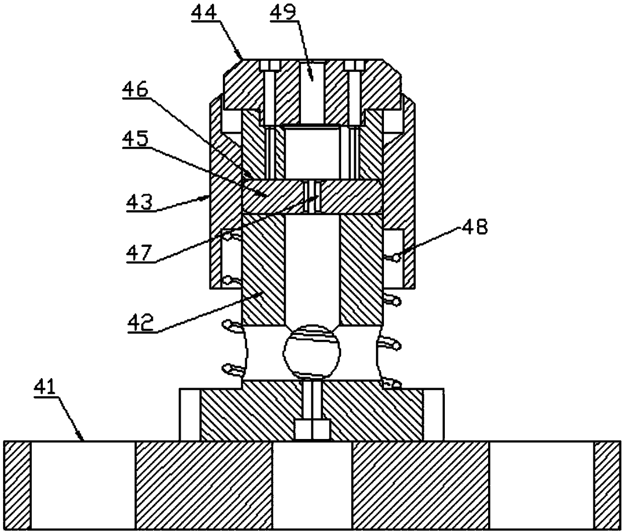
[0024] The clamping assembly 4 includes a base 41, a column 42, a movable sleeve 43, a cover 44 and a movable block 45, the column 42 is fixed on the top of the base 41 and the column 42 is provided with a placement hole 10, and the movable sleeve 43 Socketed on the outer periphery of the column 42, the column 42 is provided with a guide groove 46 arranged horizontally, and the movable block 45 is slidably connected in the guide groove 46, and the movable block 45 has two and is arranged symmetrically, and the mov...

Embodiment 2

[0028] Such as Figure 1 to Figure 6 As shown, a broach positioning and clamping device includes a workbench 1, a support platform 2, a guide seat 3 and a clamping assembly 4. The top of the workbench 1 is provided with two guide columns 6, and the support platform 2 Installed on the guide post 6 and at a distance from the top surface of the workbench 1, the guide seat 3 is installed on the top of the guide post and the guide seat 3 is provided with a guide hole 7;

[0029] The clamping assembly 4 includes a base 41, a column 42, a movable sleeve 43, a cover 44 and a movable block 45, the column 42 is fixed on the top of the base 41 and the column 42 is provided with a placement hole 10, and the movable sleeve 43 Socketed on the outer periphery of the column 42, the column 42 is provided with a guide groove 46 arranged horizontally, and the movable block 45 is slidably connected in the guide groove 46, and the movable block 45 has two and is arranged symmetrically, and the mov...


PUM


Abstract

The invention discloses a broach positioning clamping device and relates to the field of machinery. The broach positioning clamping device comprises a worktable, support platforms, guide seats and a clamping assembly. The top of the worktable is provided with two guide pillars. The support platforms are installed on the guide pillars and are separated from the top surface of the worktable by a distance. The guide seats are arranged on the top of the guide pillars and guide holes are arranged on the guide seats. The clamping assembly includes a base, a column, a movable sleeve, a cover and a movable block. The Broach positioning clamping device has simple structure and convenient operation; by moving a movable sleeve up and down, the movable block can be loosened and clamped, and then the broach can be disassembled and assembled; the whole clamping assembly adopts integrated design to simplify the structure; with the help of an elastic assembly, the movable block can slide back and forth in a guide groove by means of the moving up and down of the movable sleeve; and the guide seats can assist workers in putting a broach into the clamping assembly.

Description

technical field [0001] The invention relates to the mechanical field, in particular to a broach positioning and clamping device. Background technique [0002] A broach is a form tool used for broaching. There are multiple rows of teeth on the surface of the tool, and the size and shape of each row of teeth increases and changes sequentially from the cutting end to the cutting end. When the broach is broaching, each tooth cuts a certain thickness of metal from the workpiece, and finally obtains the required size and shape. Broaches are often used in batch and mass production to process round holes, spline holes, keyways, flat and formed surfaces, etc., with high productivity. [0003] At present, the broach needs to be clamped and positioned during the cutting work. The traditional method is prone to safety hazards and the efficiency of tool change is low. [0004] Chinese Patent Publication No. CN202804338U discloses a broach clamping device, comprising: a clamping body, ...

Claims


Application Information

Patent Timeline
IPC IPC(8): B23D41/00B23D39/00
CPCB23D39/00B23D41/00
Inventor 史沸涛吴兵成晓辉汪志强
Owner WUHU JINYI MACHINERY
Why Eureka
Try Eureka