Entering air-flotation type belt conveying mechanism

A belt conveying and air-floating technology, which is applied in the field of mold-entry air-floating belt conveying mechanism, can solve problems such as powder dropping on the edge of the pole piece, scratching on one side of the pole piece, potential safety hazards, etc., and achieve low production cost and simple structure. Effect

Pending Publication Date: 2019-02-19
GUANGDONG SUNIVE INTELLIGENT EQUIP CO LTD
View PDF0 Cites 5 Cited by
  • Summary
  • Abstract
  • Description
  • Claims
  • Application Information

AI Technical Summary

Problems solved by technology

During this process, when the pole piece cut by the cutting mechanism falls onto the belt in the conveying mechanism, the front end of the pole piece or one side of the pole piece often scratches the surface of the belt, so it is very easy to cause the edge of the pole piece to drop powder
This will bring great safety hazards to the production and use of lithium batteries in the later stage

Method used


Image

  • Entering air-flotation type belt conveying mechanism
  • Entering air-flotation type belt conveying mechanism
  • Entering air-flotation type belt conveying mechanism

Examples


Embodiment Construction

[0041] In order to make the technical problems, technical solutions and beneficial effects solved by the present invention clearer, the present invention will be further described in detail below in conjunction with the embodiments and accompanying drawings. It should be understood that the specific embodiments described here are only used to explain the present invention, not to limit the present invention.

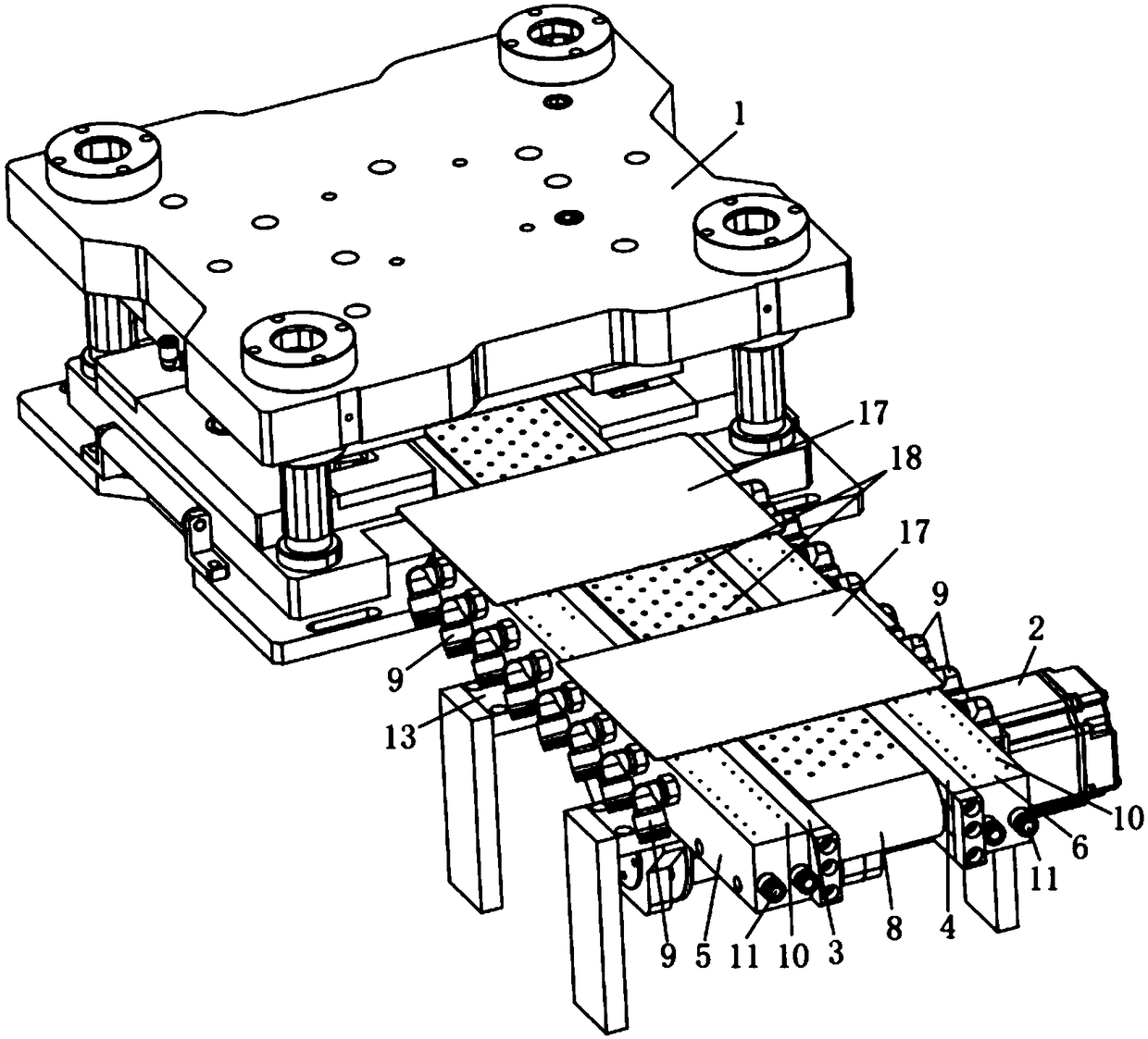
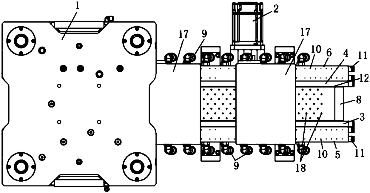
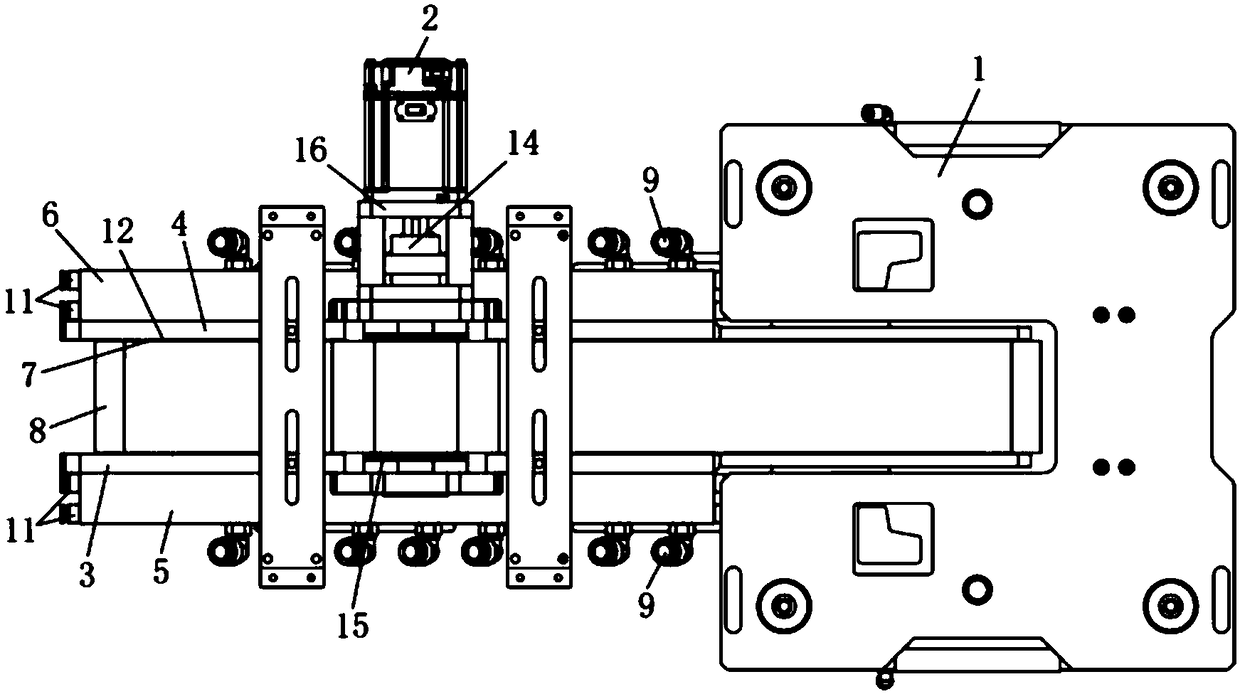
[0042] A kind of mold-entry air-floating belt conveying mechanism of this embodiment, such as Figure 1 to Figure 3 As shown, it includes a lug punching die 1, a vacuum belt conveying mechanism, a servo motor 2 drivingly connected with the vacuum belt conveying mechanism, and a left belt side plate 3 arranged on both sides of the vacuum belt conveying mechanism and used to support the vacuum belt conveying mechanism and the right belt side plate 4, the left pole piece floating plate 5 arranged on one side of the left belt side plate 3, and the right pole piece floating p...


PUM


Abstract

The invention relates to the technical field of conveying mechanisms, in particular to an entering air-flotation type belt conveying mechanism. The conveying mechanism comprises a tab punching mold, avacuum belt conveying mechanism, a servo motor in driving connection with the vacuum belt conveying mechanism, a left belt side plate, a right belt side plate, a left pole piece flotation plate and aright pole piece flotation plate; the front end of the vacuum belt conveying mechanism is arranged below the tab punching mold; the vacuum belt conveying mechanism comprises a vacuum cavity, a belt and negative-pressure gas suction pipe joints; negative-pressure holes are formed in the upper part of the vacuum cavity and the belt; ventilation cavities are formed inside the left pole piece flotation plate and the right pole piece flotation plate; a plurality of blowing holes are formed in the upper part of the left pole piece flotation plate and the upper part of the right pole piece flotationplate; and blowing end gas pipe joints are arranged at the ends of the left pole piece flotation plate and the right pole piece flotation plate. By the aid of the conveying mechanism, the phenomenonthat the front ends of pole pieces or the single edges of the pole pieces scratch the surface of the belt can be prevented, powder falling of the edges of the pole pieces can be avoided, then the polepiece quality in the pole piece forming technology can be guaranteed, and the yield and the safety of pole piece production can be improved.

Description

technical field [0001] The invention relates to the technical field of conveying mechanisms, in particular to a mold-entry air-floating belt conveying mechanism. Background technique [0002] Existing die-cutting machines are used more and more widely, and the process and quality requirements of die-cutting are getting higher and higher. For the die-cutting machine used in the manufacture of lithium batteries, not only the quality of the die-cut pole pieces is required to be high, but also the safety production process of the pole pieces is put forward higher requirements. More than 10 μm. [0003] In the prior art single-piece pole piece forming machine, the die cuts the shape of the pole piece on both sides, and then cuts it into a single pole piece by a cutting mechanism, and then transports it to the next station through a vacuum conveying mechanism. During this process, when the pole piece cut by the cutting mechanism falls onto the belt in the conveying mechanism, th...

Claims


Application Information

Patent Timeline
Patent Type & Authority Applications(China)
IPC IPC(8): B65G23/22B65G15/60B65G15/58
CPCB65G23/22B65G15/58B65G15/60
Inventor 田耀宽葛良羽罗任佐
Owner GUANGDONG SUNIVE INTELLIGENT EQUIP CO LTD
Why Eureka
Try Eureka