Prefabricated wall panel installation limiting device and construction method thereof

A technology of prefabricated wall panels and limiting devices, which is applied in the construction, building structure, processing of building materials, etc., can solve the problems of poor force capacity of the feet of the positioning tool, affecting the pre-embedding of steel bars, and reducing the construction efficiency, etc. The effect of increasing the pressure capacity, improving the construction efficiency and improving the construction quality

Pending Publication Date: 2019-02-19
CHENZHOU GRAND RESIDENCE IND CO LTD
View PDF1 Cites 7 Cited by
  • Summary
  • Abstract
  • Description
  • Claims
  • Application Information

AI Technical Summary

Problems solved by technology

[0002] During the construction process of the prefabricated wall panels of the pipe gallery, the prefabricated wall panels of the pipe gallery are composed of prefabricated layers on both sides and a sandwich layer located in the middle of the prefabricated layers on both sides. It will protrude out of the sandwich layer. The prefabricated wall panels need to be set out before hoisting, and then use the limit parts for positioning. The existing limit parts are easy to deform and weak in force during use, which affects the construction quality
[0003] CN207404679U discloses a kind of supporting positioning tool for prefabricated laminated sandwich wallboard, including support piece, positi

Method used


Image

  • Prefabricated wall panel installation limiting device and construction method thereof
  • Prefabricated wall panel installation limiting device and construction method thereof

Examples


Embodiment 1

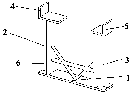
[0033] see Figure 1-2 , a prefabricated wall panel installation limit device, including a base 1, a support column and a support, the support column includes a left support column 2 and a right support column 3, the support includes a left support 4 and a right support 5, and the left support The seat 4 and the right support 5 are L-shaped, the left support column 2 and the right support column 3 are arranged on the upper surface of the base 1, and are arranged symmetrically on the two ends of the base 1 respectively, the left support 4 and the Right bearing 5 is respectively positioned at the top of left supporting column 2 and right supporting column 3, is provided with connecting rib 6 between left supporting column 2 and right supporting column 3, and connecting rib 6 is inverted A font, left supporting column 2 and right supporting column The support columns 3 are all T-shaped steel.

[0034] The sides of the left support 4 and the right support 5 are all perpendicular ...

Embodiment 2

[0037] The difference between this embodiment and Embodiment 1 is that the connecting rib is an equilateral triangle.

Embodiment 3

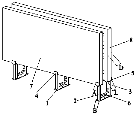
[0039] A construction method for prefabricated wall panel installation limit device, characterized in that it comprises the following steps:

[0040] 1) Position and set out the prefabricated wall panels, release the sideline position of the wall panels of the pipe gallery, and mark the position of the limit device;

[0041] 2) Install the limit device;

[0042] 3) Hoist the prefabricated wall panels so that the outer wall panels and the inner wall panels are respectively located on the left support and the right support;


PUM


Abstract

The invention discloses a prefabricated wall panel installation limiting device and a construction method thereof. The limiting device comprises a base, support columns and supports, the support columns comprise the left support column and the right support column, and the supports comprise the left support and the right support. The left support column and the right support column are disposed onthe upper surface of the base, and the left support and the right support are correspondingly located at the tops of the left support column and the right support column. Connecting ribs are arrangedbetween the left support column and the right support column. The prefabricated wall panel installation limiting device is simple in structure, convenient to construct and good in performance under stress, the interference to pre-burying of components such as steel bars and water stop plates is avoided, and the construction quality and efficiency are improved.

Description

technical field [0001] The invention relates to the technical field of construction, in particular to a prefabricated wall panel installation limiting device and a construction method thereof. Background technique [0002] During the construction process of the prefabricated wall panels of the pipe gallery, the prefabricated wall panels of the pipe gallery are composed of prefabricated layers on both sides and a sandwich layer located in the middle of the prefabricated layers on both sides. It will protrude out of the sandwich layer, and the prefabricated wall panels need to be set out before hoisting, and then positioned with limiting parts. The existing limiting parts are easily deformed and weak in force during use, which affects the construction quality. [0003] CN207404679U discloses a kind of supporting positioning tool for prefabricated laminated sandwich wallboard, including support piece, positioning piece and a plurality of legs, this positioning tool can play a p...

Claims


Application Information

Patent Timeline
IPC IPC(8): E04G21/14E04G21/18
CPCE04G21/14E04G21/1841
Inventor 张剑唐芬谭新明龙坪峰李志宏朱换良
Owner CHENZHOU GRAND RESIDENCE IND CO LTD
Why Eureka
Try Eureka