
Integrated regulating valve

A control valve, an integrated technology, applied in the direction of the lift valve, valve details, valve device, etc., can solve the problems of the overall structure of the control valve, the poor sealing effect of the control valve, and the short service life of the control valve, so as to prevent falling off Now, simple structure, prolonging the service life effect

Pending Publication Date: 2019-02-19
FLOWSERVE FLUID MOTION & CONTROL SUZHOU
View PDF0 Cites 2 Cited by
  • Summary
  • Abstract
  • Description
  • Claims
  • Application Information

AI Technical Summary

Problems solved by technology

[0003] At present, there are many types and models of regulating valves. When selecting a regulating valve, the appropriate regulating valve should be selected according to the medium parameters such as the temperature and pressure of the medium and the actual needs. In actual production, the sealing effect of the regulating valve is not good under high temperature and high pressure conditions. , easily damaged, the medium is prone to leakage, the service life of the control valve is short, the adjustment control is not precise, the deviation is large, the overall structure of the control valve is not compact, and it occupies a large installation space
At present, there is usually a coaxial through-hole on the bonnet, the upper valve body and the lower valve body, and then when they are connected by bolts, it is necessary to correspond to the through-holes one by one. This operation requires the through-holes to have higher precision. Requirements, at the same time, installation and disassembly are inconvenient, and the use occasions are limited
At the same time, the valve stem and the valve seat are usually connected by thread, which will cause it to fall off under high-frequency use and affect the service life

Method used


Image

  • Integrated regulating valve

Examples


Embodiment Construction

[0025] The present invention will be described in detail below in conjunction with specific embodiments shown in the accompanying drawings. However, these embodiments are not limited to the present invention, and structural, method, or functional changes made by those skilled in the art according to these embodiments are included within the protection scope of the present invention.

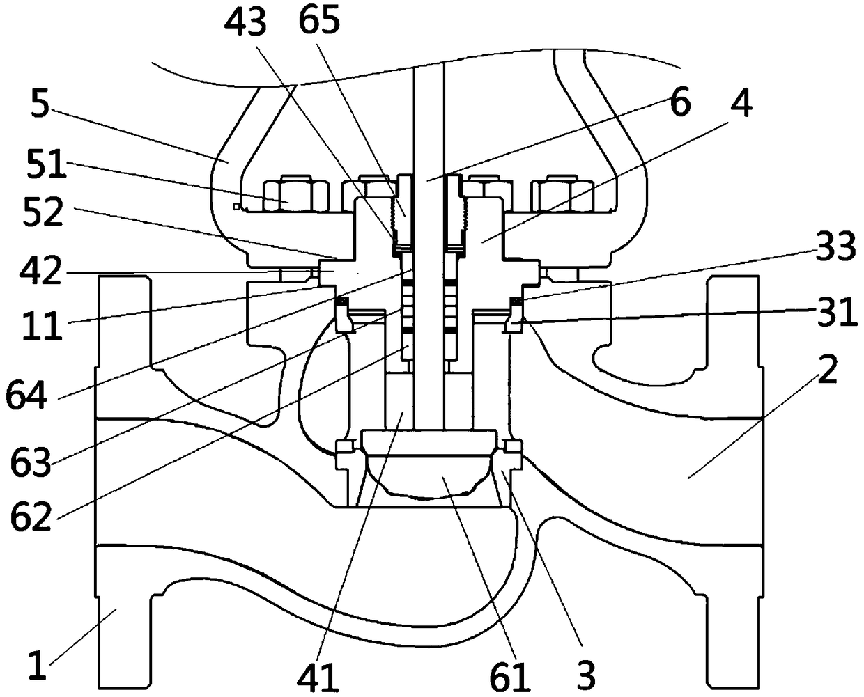
[0026] Such as figure 1 As shown, the present invention discloses an integrated regulating valve, which includes a lower valve body 1 and a flow channel 2 arranged in the lower valve body 1 , and a valve seat 3 is fixed in the flow channel 2 . An upper valve body 5 is arranged above the lower valve body 1, and a valve cover 4 is also arranged between the upper valve body 5 and the lower valve body 1, and a valve cover 4 is provided with a mounting plate penetrating along its axial direction. Hole 41; a valve stem 6 is rotatably arranged on the valve cover 4, one end of which extends through the ...


PUM


Abstract

The invention discloses an integrated regulating valve. The integrated regulating valve comprises a lower valve body and a flow passage arranged in the lower valve body, a valve seat is fixedly arranged in the flow passage, and an upper valve body is arranged above the lower valve body; a valve cover is further arranged between the upper valve body and the lower valve body, and the upper valve body and the lower valve body cooperate to limit the valve cover; the valve cover is provided with an installation hole which is through in the axial direction; and a valve stem is arranged on the valvecover in a manner of being capable of rotating by itself, one end of the valve stem penetrates through the installation hole to extend into the flow passage, a valve element is fixedly arranged at theend extending to be arranged in the flow passage through friction welding, and the valve element and the valve seat can cooperate to open or close the flow passage. The integrated regulating valve has the beneficial effects that the structure is simple and design is exquisite, reasonable design of the structure of the regulating valve is carried out, a proper sealing form is adopted to ensure thesealing reliability, the sealing effect is improved, the medium leakage is avoided, and the service life of the regulating valve is prolonged.

Description

technical field [0001] The invention relates to an integrated regulating valve. Background technique [0002] In today's industrial production and daily life, the application of control valves is becoming more and more extensive. With the complexity of production conditions and the precision of regulation and control, the requirements for the performance of control valves are also getting higher and higher. It is necessary to ensure that the control valve The precision of the adjustment must be able to maintain the reliable stability of the working performance in a complex working environment. In production, the regulating valve can be used to adjust the flow, pressure and temperature of the medium with electric actuators or pneumatic actuators. The medium passing through the regulating valve has liquid and gaseous states. Common media such as air, water, steam and corrosive media Wait. [0003] At present, there are many types and models of regulating valves. When selecti...

Claims


Application Information

Patent Timeline
IPC IPC(8): F16K1/32F16K1/36F16K1/42F16K1/48F16K27/02F16K27/08F16K41/02
CPCF16K1/32F16K1/36F16K1/42F16K1/48F16K27/02F16K27/08F16K41/02
Inventor 史强修王继东任凯雷
Owner FLOWSERVE FLUID MOTION & CONTROL SUZHOU
Learn More