A heat transfer structure and measurement and control method for optimizing heat transfer efficiency

A technology of heat transfer efficiency and heat exchange structure, applied in indirect heat exchangers, heat exchanger types, heat exchange equipment, etc., can solve the problem of low heat exchange efficiency, achieve easy distribution, good heat transfer effect, and reduce kinetic energy Effect

Active Publication Date: 2020-03-17
HEFEI GENERAL MACHINERY RES INST
View PDF5 Cites 0 Cited by
  • Summary
  • Abstract
  • Description
  • Claims
  • Application Information

AI Technical Summary

Problems solved by technology

However, in the prior art, the shell-side fluid fails to fully exchange heat with the tube-side fluid, resulting in low heat exchange efficiency

Method used


Image

  • A heat transfer structure and measurement and control method for optimizing heat transfer efficiency
  • A heat transfer structure and measurement and control method for optimizing heat transfer efficiency
  • A heat transfer structure and measurement and control method for optimizing heat transfer efficiency

Examples


Embodiment Construction

[0025] The technical solution of the present invention will be further described in detail below in conjunction with the accompanying drawings and specific embodiments.

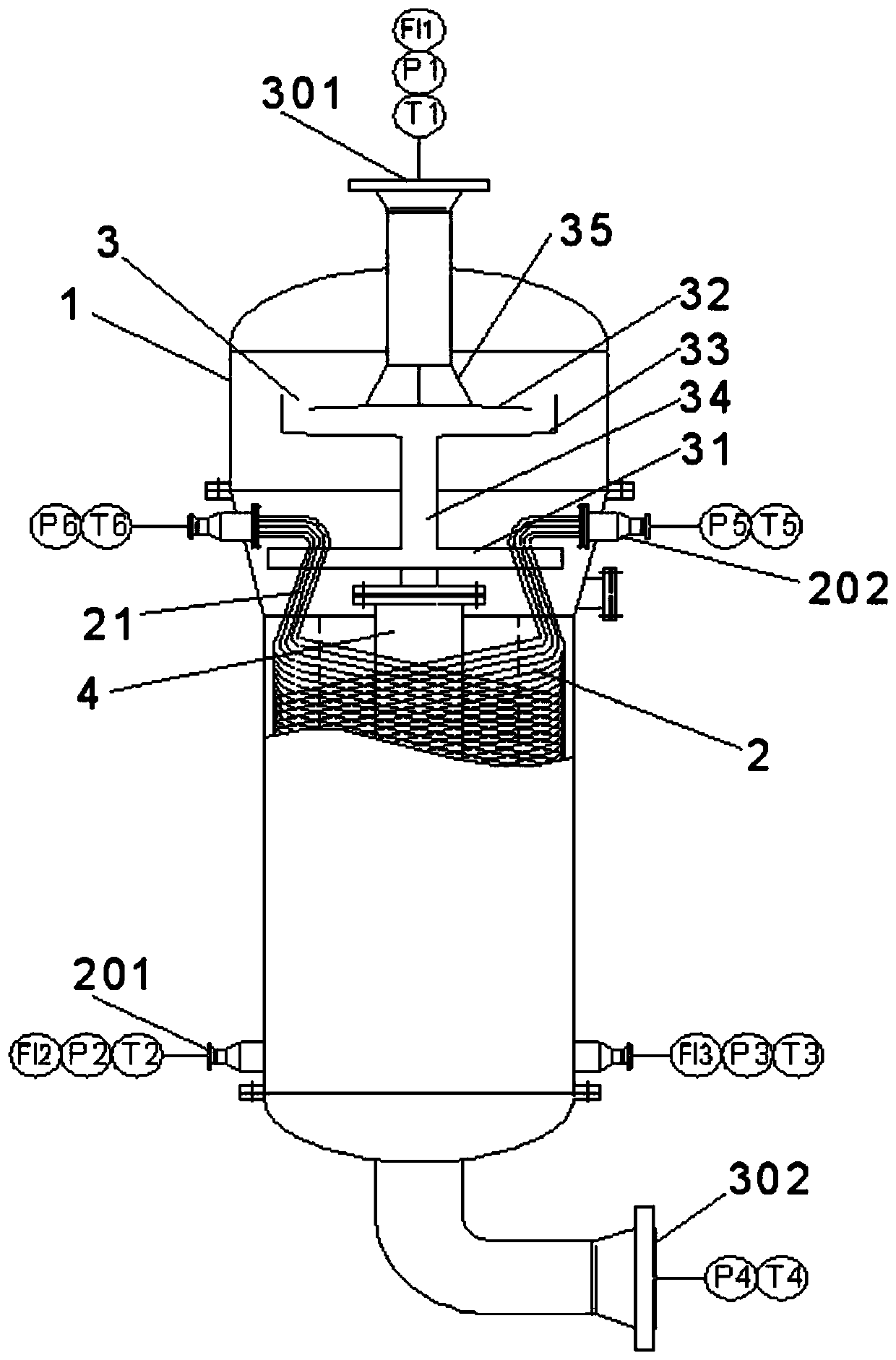
[0026] Such as figure 1 As shown, a heat exchanger with a heat exchange structure with optimized heat transfer efficiency includes heat exchange tubes arranged inside the shell 1 for the tube-side fluid to flow through and a spray device 3 for distributing the shell-side fluid; The shell 1 includes a shell body located at the bottom and sleeved on the outside of the heat exchange tube, a head body located at the top, and a conical shell airtightly connecting the body body and the head body; the inner diameter of the shell body is smaller than that of the seal body The inner diameter of the head body; the top of the head body is provided with a shell-side inlet 301 for shell-side fluid to flow in, and the bottom of the shell body is provided with a shell-side outlet 302 for shell-side fluid to flow out. The t...


PUM


Abstract

The invention relates to a heat exchange structure capable of optimizing the heat transfer efficiency and a testing control method, and relates to the technical field of heat exchange devices. The heat exchange structure comprises a heat exchange tube arranged inside a shell body and used for allowing a tube pass fluid to flow through, and a spraying device used for distributing a shell pass fluid; a tube pass inlet and a tube pass outlet which are correspondingly connected to the two ends of the heat exchange tube are arranged on the shell body, a shell pass inlet and a shell pass outlet which are correspondingly connected to the two ends of the spraying device are arranged on the shell body, the spraying device comprises a spraying part, spraying holes are formed in the bottom of the spraying part, the spraying areas of the spraying holes are matched with the arrangement area of the heat exchange tube, the hole diameter of the part, close to the liquid inlet end of the spraying part,of the spraying holes is relatively small, and the hole diameter of the part, far away from the liquid inlet end of the spraying part, of the spraying holes is relatively large. The heat exchange structure has the advantages that dismounting and replacement are convenient, the heat transfer effect is good, and the shell pass fluid is easy to distribute.

Description

technical field [0001] The invention relates to the technical field of heat exchange devices, in particular to a heat exchange structure and a measurement and control method for optimizing heat transfer efficiency. Background technique [0002] The equipment that transfers heat from hot fluid to cold fluid is called heat exchange equipment, which is widely used in oil refining, chemical industry, light industry, pharmaceutical, machinery, food processing, power and atomic energy industry sectors. The coiled tube heat exchanger is the core equipment for cooling and liquefying natural gas to -162°C through coolant in large natural gas liquefaction plants and floating liquefied natural gas production, storage and offloading devices (LNG-FPSO). Its comprehensive performance directly affects the entire LNG liquefaction Operating costs of processes and devices. The coolant entering the heat exchange device from the inlet of the shell side is generally a liquid-based gas-liquid tw...

Claims


Application Information

Patent Timeline
Patent Type & Authority Patents(China)
IPC IPC(8): F28D5/02F28F27/00
CPCF28D5/02F28F27/00
Inventor 陈永东程沛李雪吴晓红于改革何娜
Owner HEFEI GENERAL MACHINERY RES INST
Why Eureka
Try Eureka