Ultrasonic device and floating device

A technology of ultrasonic equipment and floating devices, which is applied to the structure of ultrasonic/sonic/infrasonic diagnostic equipment, ultrasonic/sonic/infrasonic diagnosis, and acoustic diagnosis, which can solve problems such as complex assembly, high cost, and complex structure, and achieve improved The compactness of the device, the simplified structure, and the good effect of linkage flexibility

Pending Publication Date: 2019-02-22
SHENZHEN MINDRAY BIO MEDICAL ELECTRONICS CO LTD +1
10 Cites 0 Cited by

AI-Extracted Technical Summary

Problems solved by technology

However, it involves multiple connecting rods and rotating hinges between connecting rods, so...

Method used

In addition, this transmission mechanism can also adopt but not limited to synchronous pulley transmission mechanism (comprising synchronous pulley and synchronous belt), pulley transmission mechanism (comprising pulley and belt) and rope transmission mechanism (comprising sheave and rope), etc., these transmission mechanisms can be set with reference to the above-mentioned sprocket chain transmission mechanism. Please refer to FIGS. 13 and 14 , in an embodiment, at least one of the first connecting arm 35 and the second connecting arm 36 may adopt the following lifting structure. The structure includes a fixed base 351 , a lifting base 359 , a connecting rod 3510 installed between the fixing base 351 and the lifting base 359 and a rope 3513 . The two ends of the connecting rod 3510 are rotatably installed on the fixed seat 351 and the lifting seat 359, the two ends of the rope 3513 are fixed on the fixed seat 351 and the liftin...

Abstract

Provided are a floating device and an ultrasonic device. Due to the fact that a first movable part and a second movable part of the floating device are arranged to perform linear reciprocating motionsalong a supporting part and meanwhile two ends of a lifting arm are hinged to the movable parts and a connecting base respectively, the positions of the first movable part and the second movable parton the supporting part can be changed when a user exerts a force on the connecting base or the lifting arm, and the first movable part and the second movable part can be away from or close to each other on the supporting part according to a stress. In addition, the angles formed by the lifting arm and the connecting base and the movable parts can automatically change according to the stress so that the connecting base can achieve multi-position movement and rotation in a plane. In addition, the lifting arm has a lifting function and is combined with other parts so that spatial floatation in the horizontal and vertical directions can be achieved. The floating device achieves multi-azimuth floatation in the horizontal and vertical directions simultaneously and also has a simpler structure,the compactness of the device can be improved, and the linkage flexibility is better.

Application Domain

Infrasonic diagnosticsSonic diagnostics +1

Technology Topic

EngineeringAzimuth +4

Image

  • Ultrasonic device and floating device
  • Ultrasonic device and floating device
  • Ultrasonic device and floating device

Examples

  • Experimental program(1)

Example Embodiment

[0062] The present invention will be further described in detail below through specific embodiments in conjunction with the accompanying drawings. Wherein similar elements in different embodiments have used associated similar element numbers. In the following embodiments, many details are described so that the present application can be better understood. However, those skilled in the art will readily recognize that some of the features may be omitted under different circumstances, or may be replaced by other elements, materials, and methods. In some cases, some operations related to the present application are not shown or described in the specification, in order to avoid the core part of the present application from being overwhelmed by excessive description, and for those skilled in the art, these are described in detail. The relevant operations are not necessary, and they can fully understand the relevant operations according to the descriptions in the specification and general technical knowledge in the field.
[0063] Additionally, the features, acts, or characteristics described in the specification may be combined in any suitable manner to form various embodiments. At the same time, the steps or actions in the method description can also be exchanged or adjusted in order in a manner obvious to those skilled in the art. Therefore, the various sequences in the specification and drawings are only for the purpose of clearly describing a certain embodiment and are not meant to be a necessary order unless otherwise stated, a certain order must be followed.
[0064] The serial numbers themselves, such as "first", "second", etc., for the components herein are only used to distinguish the described objects, and do not have any order or technical meaning. The "connection" and "connection" mentioned in this application, unless otherwise specified, include both direct and indirect connections (connections).
[0065] This embodiment provides an ultrasonic device, which may be, for example, an ultrasonic diagnostic apparatus or other ultrasonic devices.
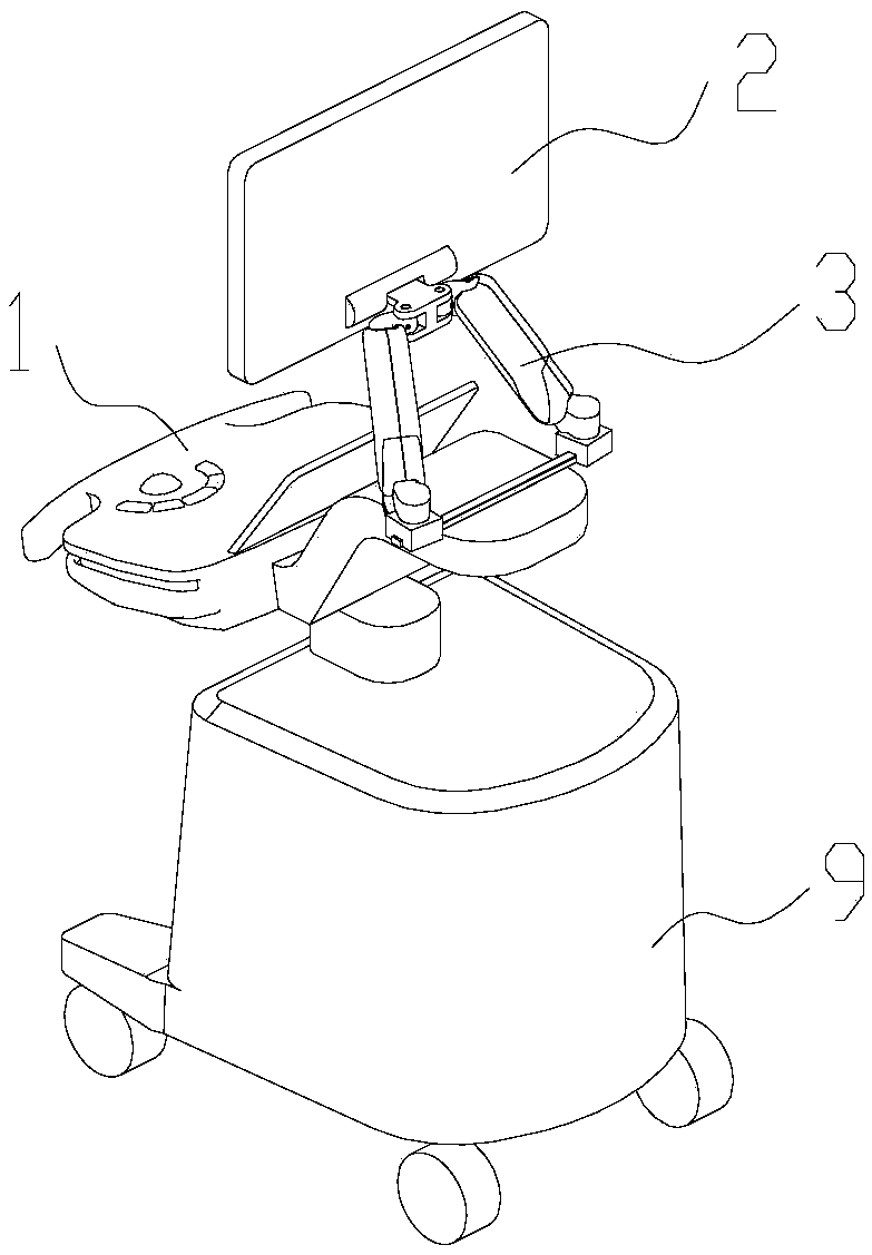
[0066] Please refer to figure 1 and 2 , In an embodiment, the ultrasonic device includes a control panel 1 , a display device 2 , a floating device 3 and a host 9 . The display device 2 can use various display devices to display various images or other electronic information, for example, information used to display the processing process, the result of the processing completed, or other information. The display device 2 may be a display screen or a touch display device with a touch function. The control panel 1 is generally provided with buttons, knobs, etc., and the user can operate the ultrasonic diagnostic apparatus through the control panel 1 . In this embodiment, the control panel 1 is installed on the host 9 , and the display device 2 is installed on the control panel 1 . The ultrasonic device can also be configured with components such as rollers, handles, etc., which are not repeated here.
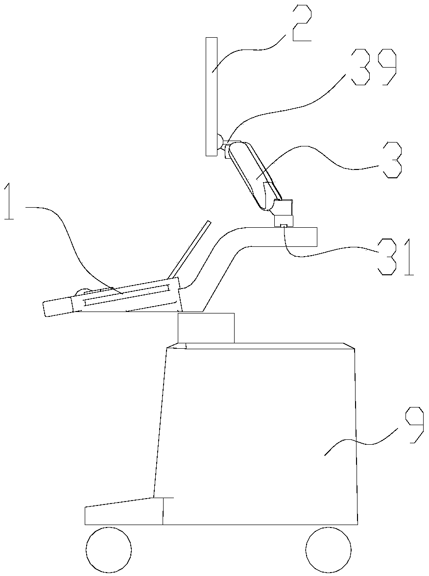
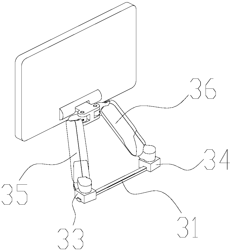
[0067] The floating device 3 has a spatial floating function and can be used to switch the display device 2 between various positions in space. Please refer to image 3 and 4 , the floating device 3 includes a supporting member 31 , a moving member, a lifting arm and a connecting seat 39 .
[0068] The moving member includes a first moving member 33 and a second moving member 34 . The first moving member 33 and the second moving member 34 are mounted on the support member 31 in a manner capable of reciprocating movement along a linear trajectory on the support member 31 . The first moving member 33 and the second moving member 34 can reciprocate along the same linear trajectory. When the first moving member 33 and the second moving member 34 are acted by an external force, they can perform linear reciprocating motion along the supporting member 31 .
[0069] The lift arm includes a first lift arm 35 and a second lift arm 36 . The first lift arm 35 and the second lift arm 36 both have a first end and a second end that can be lifted and lowered relative to the first end. The first end of the first lifting arm 35 is mounted on the first moving member 33 and can rotate relative to the first moving member 33 around a first rotation axis. The first end of the second lifting arm 36 is mounted on the second moving member 34 and can rotate relative to the second moving member 34 around the second rotation axis. In this way, the first lifting arm 35 and the second lifting arm 36 can rotate around the first moving member 33 and the second moving member 34 respectively, and the rotation angles can also be different.
[0070] The second end of the first lifting arm 35 is connected with the connecting seat 39 and can rotate relative to the connecting seat 39 around the third rotation axis. The second end of the second lifting arm 36 is connected with the connecting seat 39 and can rotate relative to the connecting seat 39 around the fourth rotation axis. That is, the first end and the second end of the lift arm are rotatably connected with the connecting piece and the connecting seat 39, respectively. The connecting base 39 can be moved in the horizontal and vertical directions through the lifting arm and the moving member. The support 31 of the floating device 3 is fixedly mounted on the control panel 1 , and the connecting base 39 of the floating device 3 is connected to the display device 2 , so that the display device 2 can be spatially displaced relative to the control panel 1 through the floating device 3 .
[0071] In addition, in some other embodiments, the support member 31 of the floating device 3 can also be fixedly installed on the host 9 , so that the display device 2 can be floated and displaced relative to the host 9 instead of the control panel 1 through the floating device 3 .
[0072] Please refer to Figure 5-8 , because the two ends of the lifting arm are hinged with the moving member and the connecting seat 39 respectively, and the moving member is mounted on the supporting member 31 in a movable manner, so the user can change the first position when applying force to the connecting seat 39 or the lifting arm The positions of the first moving member 33 and the second moving member 34 on the supporting member 31, and the angle between the lifting arm and the connecting seat 39 and the moving member can also change according to the force, so that the connecting seat 39 can be in the plane To achieve multi-position movement and rotation. At the same time, the lifting arm itself has a lifting function, so in combination with other components, the connecting seat 39 and the components (such as the display device 2 ) mounted on the connecting seat 39 can be spatially floated in the horizontal and vertical directions, including the left and right Move, move up and down, move back and forth, and rotate. This structure realizes multi-directional floating in horizontal and vertical directions at the same time, and also has a more simplified structure, lower cost and convenient maintenance. Moreover, the modularization of the overall structure can be realized, the compactness of the device can be improved, the number of parts is less, and the linkage flexibility is better.
[0073] However, the ultrasonic apparatus adopts the floating device 3, so the display device 2 can be floated at multiple positions in space, so that the display device 2 can be easily adjusted to a position suitable for the user. Moreover, the structure of the floating device 3 is more simplified and compact, which is beneficial to the miniaturization of the ultrasonic equipment. At the same time, the floating device 3 has good linkage flexibility and is more convenient for the user to operate. The floating device 3 has a larger operating range and can float in more space.
[0074] Of course, although ultrasonic equipment is used as an example in this embodiment, it should be noted that the floating device 3 can also be applied to other equipment that needs to achieve spatial floating, and is not limited to ultrasonic equipment.
[0075] Further, the first moving member 33 and the second moving member 34 are mounted on the supporting member 31 in a manner capable of reciprocating movement along a linear trajectory on the supporting member 31 , which can be realized in various ways. For example, in one embodiment, the support member 31 has a linear moving track, and the first moving member 33 and the second moving member 34 move on the moving track. Of course, in other embodiments, the support member 31 may not have a definite linear moving track, but the limit of the moving direction of the moving member is realized through a mechanical structure, so that the moving member can only reciprocate along a straight line.
[0076] Please refer to image 3 and Figure 4 In one embodiment, the support member 31 has a linear slide rail, and the moving members (the first moving member 33 and the second moving member 34 ) are sliders, and the sliders are slidably installed on the linear slide rails.
[0077] above image 3 and 4 Only one example is shown, and the way of cooperation between the support 31 and the moving part can be, but not limited to, the connection between the sliding rail and the slider, the connection between the sliding groove and the sliding block, the connection between the pulley and the sliding rail, and the straight line. One of the guide sleeve form, the pulley rope form, the rack and pinion transmission form and the connecting rod transmission form. Of course, not all structures capable of realizing linear reciprocating motion of the moving member relative to the supporting member 31 are not listed here. Structures not listed to achieve this purpose are still included in the present application.
[0078]Preferably, in an embodiment, the first rotation axis and the second rotation axis are parallel to each other and at the same time perpendicular to the linear reciprocating movement direction of the moving member. This makes it easy to drive the first moving member 33 and the second moving member 34 to move on the support member 31 when adjusting the display device 2 .
[0079] Preferably, in an embodiment, the third axis of rotation and the fourth axis of rotation are parallel or coincident with each other. Please refer to image 3 and 4 , the first lifting arm 35 and the second lifting arm 36 are respectively connected to the two ends of the connecting seat 39 through different shafts 395 and 396 in rotation, so that the third rotation axis and the fourth rotation axis are parallel to each other. In other embodiments, the first lifting arm 35 and the second lifting arm 36 can be installed coaxially, so that the third rotation axis and the fourth rotation axis coincide. When the first lift arm 35 and the second lift arm 36 are installed coaxially, the rotation angle of the connection seat 39 relative to the first lift arm 35 and the second lift arm 36 can be larger.
[0080] Preferably, in one embodiment, the first axis of rotation, the second axis of rotation and the third axis of rotation (or the fourth axis of rotation) are parallel to each other. In this way, when the user exerts a force on the floating device 3, the rotational movements of the rotation axes can be effectively matched to avoid interference between the movements, so that the change of the floating device 3 can be smoother and more stable.
[0081] It should be noted that, in this article, when two axes of rotation are referred to as being "perpendicular to each other", it may refer to: when the two axes of rotation are in the same plane, they are perpendicular to each other; when the two axes of rotation are not in the same plane When they are in the same plane, the two are perpendicular to each other in space, that is, the projection of one rotation axis on the plane where the other rotation axis is located is perpendicular to the other rotation axis.
[0082] In this context, when two axes of rotation "intersect", it may mean that when the two axes of rotation are in the same plane, the two intersect each other; when the two axes of rotation are not in the same plane, where The projection of one axis of rotation on the plane of the other axis of rotation intersects the other axis of rotation.
[0083] Further, the lifting arm is a connecting arm with a lifting function, and various structures can be used to realize the lifting function. For example, the lifting arm can use a parallelogram mechanism to realize the lifting function.
[0084] Please refer to Figure 9 and 10 , taking the first lift arm 35 as an example, the first lift arm 35 includes a fixed seat 351 , a connecting rod 354 , a lift seat 359 and a lower bracket 358 . The fixed seat 351 , the connecting rod 354 , the lifting seat 359 and the lower bracket 358 are rotatably connected in sequence to form a parallel four-bar linkage mechanism. When the lifting seat 359 is moved, the position of the fixing seat 351 can be kept unchanged, and the lifting seat 359 can move up and down.
[0085] The fixed seat 351 , the lifting seat 359 , the connecting rod 354 and the lower bracket 358 of the first lifting arm 35 form a parallel four-link structure through the pin shaft 71 , the pin shaft 75 , the pin shaft 81 and the pin shaft 85 , which can ensure that the lifting seat 359 is in the The function of always being parallel to the fixed seat 351 during the lifting process.
[0086] The fixed seat 351 is rotatably connected with the first moving member 33 , so as to realize the rotational connection between the first lifting arm 35 and the first moving member 33 . The lifting seat 359 is rotatably connected with the connecting seat 39 , so as to realize the rotatable connection between the first lifting arm 35 and the connecting seat 39 .
[0087] Specifically, please refer to Figure 4 , the fixed seat 351 of the first lifting arm 35 is connected to the first moving member 33 and is rotatable around the rotating shaft 335 . Similarly, the fixed seat 361 of the second lifting arm 36 is connected to the second moving member 34 and can be rotated around the rotating shaft 345 . The lifting seat 359 of the first lifting arm 35 is connected to the connecting seat 39 through the rotating shaft 395 and is rotatable around the rotating shaft 395 . Similarly, the lifting seat 359 of the second lifting arm 36 is connected to the connecting seat 39 through the rotating shaft 396 and is rotatable around the rotating shaft 396 .
[0088] Of course, the above lift structure is only an example, and at least one of the first lift arm 35 and the second lift arm 36 may adopt this structure. Or, both of them use other lifting structures to realize the lifting function. For example, the lifting structure can also include, but is not limited to, the simplified parallel four-link form shown in this case, the traditional four-link system, the parallel four-link system, and the approximate parallel lifting of a single link driven by a chain or rope.
[0089] Further, in order to ensure that the lift arm can be stabilized at the current height at any time, so that the display device can be stopped at any position in the lift, in an embodiment, at least one of the first lift arm 35 and the second lift arm 36 has a damping force balance. The mechanism is used to stabilize the first lift arm 35 and the second lift arm 36 at the set height. Since the first lifting arm 35 and the second lifting arm 36 are jointly connected to the connecting base 39, after one of them is stabilized at the set height, the other cannot move accordingly.
[0090] The damping force balance mechanism can take many forms, including but not limited to gas spring form, tension spring form including compression spring form, constant force spring form such as coil spring form, torsion spring form, internal friction damping structure, etc.
[0091] Please refer to Figure 9 and 10 In one embodiment, the damping force balance mechanism includes a compression spring 356 and a damping assembly 355 . The damping assembly 355 and the compression spring 356 are sleeved on the connecting rod 354 . The damping assembly 355 is connected to the fixed seat 351 through a transmission rod 352 , and two ends of the transmission rod 352 are rotatably connected to the damping assembly 355 and the fixed seat 351 respectively. The rotation axis of the transmission rod 352 relative to the fixed seat 351 is offset from the rotation axis of the connecting rod 354 relative to the fixed seat 351 . Both ends of the compression spring 356 are compressed by the damping assembly 355 and the connecting rod 354 respectively. The design can ensure that the load force value of the lifting seat 359 is relatively constant during the lifting process, and the lifting arm has a certain damping force value, which can make the display device 2 stop stably at any position during the lifting process. The first connecting arm 35 may also be provided with an upper casing 61 to cover the internal structures such as the compression spring 356 .
[0092] For example, a damping assembly 355 may include a sliding block and a spring provided in the sliding block, the sliding block is sleeved on the connecting rod 354 and is connected to the fixed seat 351 through the support connecting pieces on both sides. The two ends of the support connector are respectively connected to the slider and the fixed seat 351 for rotation. For example, the support connector can be connected to the fixed seat 351 in a coaxial rotation with the lower bracket 358 . The damping assembly 355 can form a damping force balance for the connecting rod 354, so that the connecting rod 354 can stably stay at a required position.
[0093] Further, the parallel four-bar linkage mechanism has four mutually parallel fifth rotation axes (axis directions of the pins 71 , 75 , 81 , 85 ). The fifth rotation axis is perpendicular to the first rotation axis and the second rotation axis, and the fifth rotation axis and the linear reciprocating direction of the moving member are parallel to each other. In this way, the lifting movement of the lifting arm, the rotation of the lifting arm and the moving member, and the linear movement of the moving member and the support member 31 can form a more effective cooperation, so that the floating movement of the floating device 3 is more smooth and stable.
[0094] The fifth rotation axis, the third rotation axis and the fourth rotation axis can also be perpendicular to each other, so that the lifting movement of the lifting arm and the rotation of the lifting arm and the connecting seat 39 can form a more effective cooperation, so that the floating movement is more smooth and stable .
[0095] In the above-mentioned parallel four-bar linkage mechanism, the lower bracket 358 can also be omitted, and the fixing base 351 and the lifting base 359 are only connected by the connecting rod 354 . In this case, a corresponding rotational stabilization mechanism, such as a rotation damping device, needs to be provided at the rotational connection between the connecting rod 354 and the lifting seat 359 to ensure that the lifting seat 359 can be stabilized at various angles relative to the connecting rod 354 .
[0096] Of course, the above lifting structure is only an example, and at least one of the first connecting arm 35 and the second connecting arm 36 may adopt this structure. Or, both of them use other lifting structures to realize the lifting function. For example, the lifting structure can also include, but is not limited to, the simplified parallel four-link form shown in this case, the traditional four-link system, the parallel four-link system, and the approximate parallel lifting of a single link driven by a chain or rope.
[0097] In one embodiment, the lift arm may include a fixed base, a lift base, a connecting rod installed between the fixed base and the lift base, and a transmission mechanism, and both ends of the connecting rod are rotatably mounted on the fixed base and the lift base. The transmission mechanism includes two transmission wheels and a transmission part sleeved on the two transmission wheels, and the two transmission wheels are respectively fixed on the fixed seat and the lifting seat.
[0098] Please refer to Figure 11 and 12 , In an embodiment, at least one of the first connecting arm 35 and the second connecting arm 36 may adopt the structure of the following link and transmission mechanism. The structure includes a fixed base 351, a lift base 359, a connecting rod 3510 installed between the fixed base 351 and the lift base 359, and a transmission mechanism. like Figure 11 and 12 As shown, both ends of the connecting rod 3510 are rotatably installed on the fixed seat 351 and the lifting seat 359. The transmission mechanism used in the figure is a sprocket chain transmission mechanism, and the two sprockets 3512 are fixedly installed on the fixed seat 351 and On the lift seat 359, the chain 3511 is sleeved on the two sprockets 3512. The lifting seat 359 can be lifted and lowered relative to the fixed seat 351 under the action of external force, so as to realize the lifting function.
[0099] In addition, the transmission mechanism can also adopt but not limited to synchronous pulley transmission mechanism (including synchronous pulley and synchronous belt), pulley transmission mechanism (including pulley and belt) and rope transmission mechanism (including sheave and rope), etc. , these transmission mechanisms can be set with reference to the above-mentioned sprocket chain transmission mechanism. Please refer to Figure 13 and 14 In one embodiment, at least one of the first connecting arm 35 and the second connecting arm 36 may adopt the following lifting structure. The structure includes a fixed base 351 , a lift base 359 , a connecting rod 3510 installed between the fixed base 351 and the lift base 359 , and a rope 3513 . The two ends of the connecting rod 3510 are rotatably installed on the fixed seat 351 and the lifting seat 359 , the two ends of the rope 3513 are fixed on the fixed seat 351 and the lifting seat 359 , and the fixed point position 3516 of the rope 3513 and the hinge point of the two ends of the connecting rod 3510 3517, 3518 positions do not overlap. The lifting seat 359 can be lifted and lowered relative to the fixed seat 351 under the action of external force, so as to realize the lifting function. A support protrusion 3514 is formed in the middle of the connecting rod, which forms a sliding support for the middle 3515 of the rope 3513, so as to ensure that the lengths of the upper and lower parts of the rope 3513 can be transformed in a balanced manner during the lifting process.
[0100] Please refer to Figure 15 and 16 In one embodiment, at least one of the first connecting arm 35 and the second connecting arm 36 may adopt the following lifting structure. The structure includes a fixed base 351, a lift base 359, a connecting rod 3510 installed between the fixed base 351 and the lift base 359, an angle detection device and a drive locking device (the angle detection device and the drive locking device are not shown in the figure). Both ends of the connecting rod 3510 are rotatably mounted on the fixing base 351 and the lifting base 359 . The angle detection device is used to detect the angles a and b between the two ends of the connecting rod 3510 and the fixed seat 351 and the lifting seat 359 respectively. During the lifting process, the angle detection device detects the angles a and b of the hinge points 3517 and 3518 at both ends of the connecting rod 3510, and feeds back the data to the drive locking device. The driving locking device can drive the lifting base 359 to rotate relative to the connecting rod 3510 , and drive the connecting rod 3510 to rotate relative to the fixing base 351 . According to the existing design formula, it can be ensured that the plane of the lifting seat 359 is parallel to the plane of the fixing seat 351 during any lifting process. The above movement can be locked when the locking device is actuated to activate the locking function.
[0101]In order to avoid an excessive rotation angle between the lifting arm and the moving member, in one embodiment, at least one of the first lifting arm 35 and the first moving member 33 is provided with a first lower rotation limiting pin that moves integrally. The corresponding other one is provided with a first lower limit groove which is matched with the first lower rotation limit pin. The first lower rotation limiting pin is restricted to rotate within the region of the first lower limiting groove.
[0102] Please refer to Figure 17 , the first lower rotation limit pin 684 can be fixed on the fixing seat 351 of the first lifting arm 35 (only the lower rotation limit pin 684 is schematically drawn in the figure, and the fixing seat 351 is omitted), and the first lower limit The position slot 681 is opened on the first moving member 33 (only a part of the first moving member 33 is shown in the figure). The first lower limiting groove 681 adopts an arc-shaped groove arranged around the first rotation axis. The first lower rotation limiting pin 684 extends into the arc-shaped groove and is limited to move in the arc-shaped groove, so that the relative rotation angle of the first lifting arm 35 and the first moving member 33 is controlled within a set range.
[0103] Of course, in some embodiments, at least one of the second lifting arm 36 and the second moving member 34 may be provided with a second lower rotation limit pin that moves integrally, and the corresponding other one is provided with a second lower rotation limit pin. The second lower limit groove matched with the limit pin. The second lower rotation limiting pin is restricted to rotate within the region of the second lower limiting groove.
[0104] Further, in order to realize that the display device can be stopped stably at any position in the plane, the adjustment of the joint rotation damping force can also be provided. The lift arm has the function of adjusting the rotational damping force relative to the moving member.
[0105] Further, in an embodiment, at least one of the first lifting arm 35 and the connecting base 39 is provided with a first upper rotation limit pin that moves integrally, and the corresponding other is provided with a first upper rotation limit pin. The matching first upper limit slot. The first upper rotation limiting pin is restricted to rotate within the region of the first upper limiting groove.
[0106] Please refer to Figure 18 , the first upper rotation limit pin 3814 can be fixed on the connecting seat 39 (only the upper rotation limit pin 3814 is shown in the figure, the connecting seat 39 is omitted), and the first upper limit slot 3811 is opened in the first lifting arm 35 on the lift seat 359. The first upper limit groove 3811 adopts an arc-shaped groove arranged around the third rotation axis. The first upper rotation limiting pin 3814 extends into the arc-shaped groove and is limited to move in the arc-shaped groove, so that the relative rotation angle of the first lifting arm 35 and the connecting base 39 is controlled within a set range.
[0107] Similarly, in order to realize that the display device can be stopped stably at any position in the plane, the adjustment of the joint rotation damping force can also be provided. This enables the lifting arm to have the function of adjusting the rotational damping force relative to the connecting seat 39 .
[0108] Of course, in some embodiments, at least one of the second lifting arm 36 and the connecting base 39 may be provided with a second upper rotation limit pin that moves integrally, and the corresponding other one is provided with a second upper rotation limit pin. The second upper limit groove is matched with the pin, and the second upper rotation limit pin is restricted to rotate in the area of ​​the second upper limit groove.
[0109] On the other hand, please refer to Figure 4 and Figure 19 , in one embodiment, a damping shaft assembly 65 is also included. The damping shaft assembly 65 includes a base 651 and a damping shaft 653 mounted on the base 651 . The base 651 is fixed to the display device 2 . The connection base 39 is connected with the damping shaft 653 , so that the display device 2 can rotate relative to the connection base 39 around the sixth rotation axis. The sixth axis of rotation is perpendicular to the third axis of rotation and the fourth axis of rotation. Under the action of the damping shaft assembly 65, the display device 2 can follow the Figure 19 The rotation direction shown is rotated at a certain angle and stabilized at this angle to meet different angle requirements.
[0110] Please refer to Figure 20 and 21 , an embodiment also provides an ultrasonic device, specifically an ultrasonic diagnostic instrument. The supporting member 31 of the floating device 3 is connected to the host 9 , and the connecting base 39 of the floating device 3 is fixedly installed on the control panel 1 , that is, the floating device 3 is used to support the control panel 1 in a floating manner.
[0111] Also, please refer to Figure 22 , an embodiment also provides an ultrasonic device, the support 31 of the floating device 3 is fixedly installed on the control panel 1 , and the connecting seat 39 of the floating device 3 is connected to the host 9 . That is, the floating device 3 is installed upside down. The inverted floating device 3 can also be applied between the display device 2 and the control panel 1 and between the display device 2 and the host 9 .
[0112] In a word, the floating device 3 is installed between the control panel 1 and the display device 2 , can also be installed between the control panel 1 and the host 9 , and can also be installed between the display device 2 and the host 9 . Both the support member 31 and the connection base 39 of the floating device 3 can be connected to the control panel 1 , the display device 2 and the host 9 as a connection structure.
[0113] Further, in the above various embodiments, there may also be at least two floating devices 3 . At least one floating device 3 is arranged between the host 9 and the control panel 1, and at least one floating device 3 is arranged between the display device 2 and the control panel 1, so that more floating devices 3 are combined to form more floating devices Variety.
[0114] The above specific examples are used to illustrate the present invention, which are only used to help understand the present invention, and are not intended to limit the present invention. For those skilled in the art to which the present invention pertains, according to the idea of ​​the present invention, several simple deductions, modifications or substitutions can also be made.

PUM

no PUM

Description & Claims & Application Information

We can also present the details of the Description, Claims and Application information to help users get a comprehensive understanding of the technical details of the patent, such as background art, summary of invention, brief description of drawings, description of embodiments, and other original content. On the other hand, users can also determine the specific scope of protection of the technology through the list of claims; as well as understand the changes in the life cycle of the technology with the presentation of the patent timeline. Login to view more.

Similar technology patents

Body condition measuring device

InactiveUS20050234351A1simple structure
Owner:DENSO CORP

Magnetic cooling apparatus and control method thereof

ActiveUS20130180263A1simple structure
Owner:SAMSUNG ELECTRONICS CO LTD

Dual-Drivetrain of Power-Assist Vehicle

InactiveUS20100181130A1enhance uphill momentumsimple structure
Owner:CHOU WEN CHENG

Classification and recommendation of technical efficacy words

  • Simple structure

Sharing system for air-conditioning coat

InactiveCN107440179ASimple structureeasy to wear
Owner:QINGDAO HAIER AIR CONDITIONER GENERAL CORP LTD

Feeding device of sorter of batteries plate

InactiveCN101357717ASimple structurecooperate well
Owner:NANJING NORMAL UNIVERSITY

Emergency parachuting device and method for multiple-rotor unmanned aerial vehicle

InactiveCN103895870Aavoid aircraft crashSimple structure
Owner:SOUTH CHINA AGRI UNIV +1
Why Eureka
Try Eureka