Electrostatic fume purifying device with composite layer type electric field

An oil fume purification, electrostatic technology, applied in electrode conveying device, electrostatic separation, electrode structure and other directions, can solve the problems of insufficient effective stun area, small number of stun electrodes, short oil fume residence time, etc., to improve the effect of oil fume purification , Good fume purification effect, prolonging the effect of residence time

Pending Publication Date: 2019-02-22
刘让宗
View PDF1 Cites 2 Cited by
  • Summary
  • Abstract
  • Description
  • Claims
  • Application Information

AI Technical Summary

Problems solved by technology

[0003] At present, there are two commonly used electrostatic oil fume purifiers: one is a purification device with a honeycomb cylinder structure, but this type of purification device has shortcomings such as a small number of start-up electrodes and insufficient residence time of oil fume, resulting in low purification efficiency. The purification effect is poor; the other is a purification device with a plate structure, such as the invention patent with the patent number "ZL201310602354.9" and the patent name "Electrostatic Fume Purification Device". The inlet is equipped with a corona area composed of corona wires and a plate-type collection area arranged along the direction of airflow to cooperate with the purification of oil fume
However, this plate-type purification device has shortcomings such as insufficient effective corona initiation area and short residence time of oil fume, which causes some oil fume molecules to pass directly through the corona area without ionization and charging, resulting in oil fume and oil mist particles. It cannot be completely purified and removed, and the purification effect is poor

Method used


Image

  • Electrostatic fume purifying device with composite layer type electric field
  • Electrostatic fume purifying device with composite layer type electric field
  • Electrostatic fume purifying device with composite layer type electric field

Examples


Embodiment Construction

[0029] The following are only preferred embodiments of the present invention, and therefore do not limit the protection scope of the present invention.

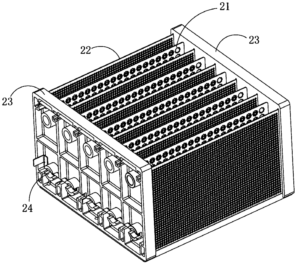
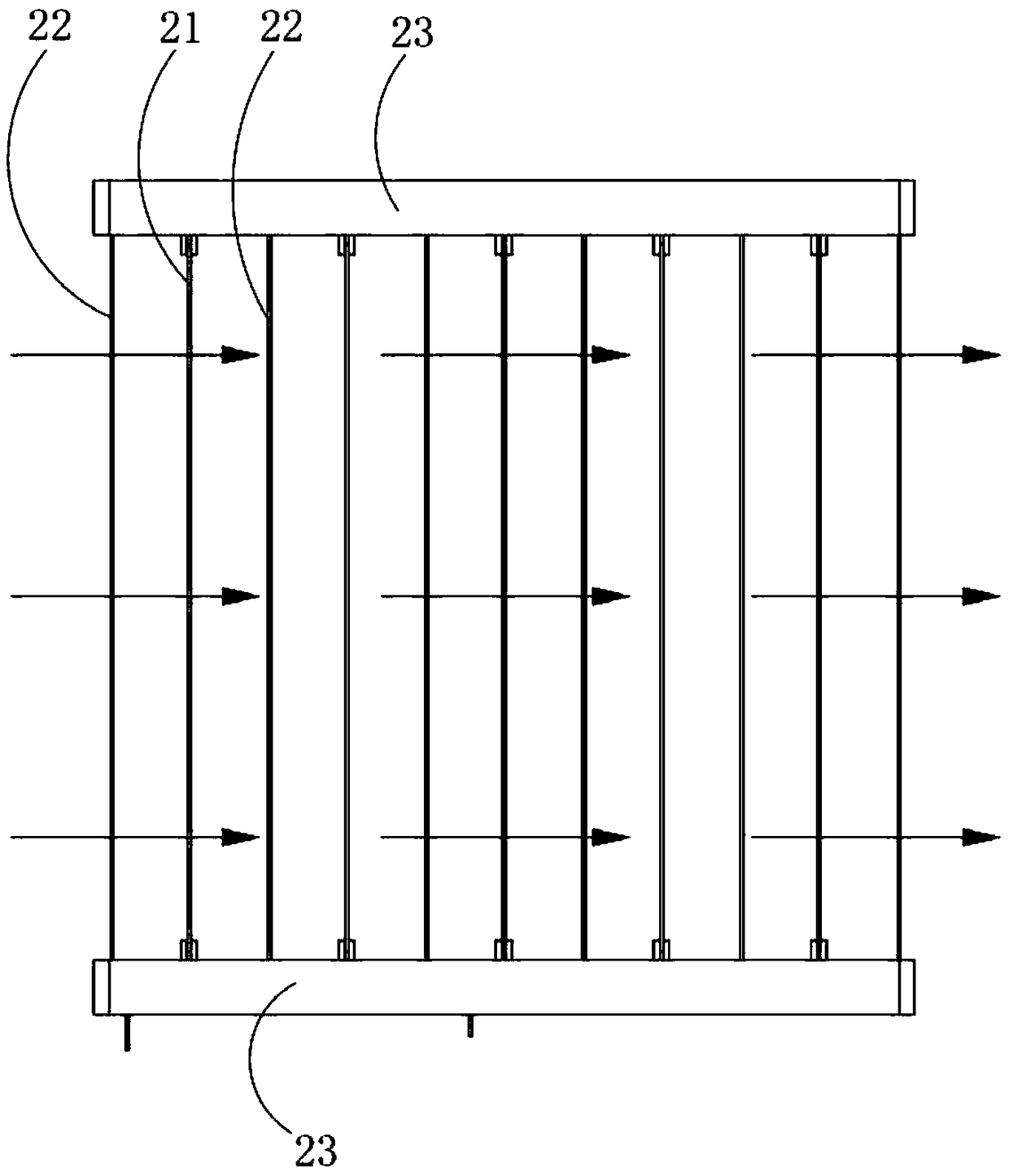
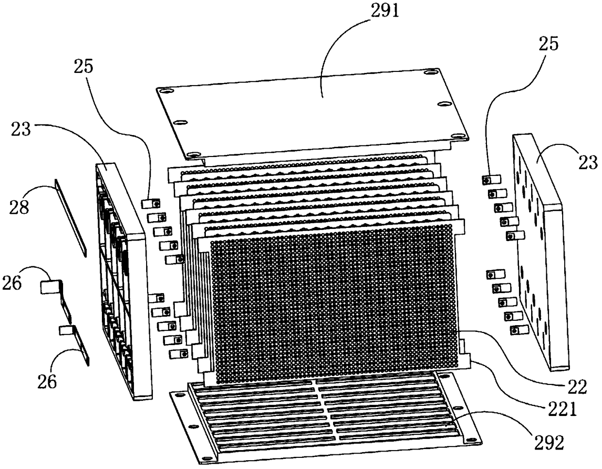
[0030] An electrostatic oil fume purification device with a composite layer electric field, such as Figure 1 to Figure 5 As shown, a box is included, one end of the box is provided with an air inlet, the other end of the box is provided with an air outlet, and at least one high-voltage electrostatic field group is arranged in the box, and the high-voltage electrostatic field group includes at least one cathode plate 21 and at least one An anode plate 22, all cathode plates 21 and anode plates 22 are alternately stacked and installed in the casing along the airflow direction, each cathode plate 21 is provided with a plurality of corona opening holes 211, and the edge of each corona opening hole 211 is convex At least one corona electrode 212 is molded; each anode plate 22 is provided with a plurality of ventilation holes. Du...


PUM


Abstract

The invention discloses an electrostatic fume purifying device with a composite layer type electric field. The electrostatic fume purifying device comprises a box body, an air inlet is formed in one end of the box body, an air outlet is formed in the other end of the box body, at least one high voltage electrostatic field set is arranged in the box body and comprises at least one cathode plate andat least one anode plate, the cathode plates and the anode plates are alternately stacked in the box body at intervals in the airflow direction, each cathode plate is provided with multiple corona inception holes, and the edge of each corona inception hole is protruded to form at least one corona inception electrode; and each anode plate is provided with multiple air holes. By means of the structure, fume can form flocculant flow, and fume sufficiently passes through the corona inception holes; and compared with an existing fume purifying device with the same size, the effective corona inception area is higher, the purifying efficiency is higher, and the purifying effect is better.

Description

technical field [0001] The invention relates to the technical field of electrostatic oil fume purification devices, in particular to an electrostatic oil fume purification device with a composite layer electric field. Background technique [0002] The electrostatic oil fume purifier uses the electrons emitted in the high-voltage electric field and the negative ions generated by the electrons colliding with air molecules to capture the oil fume and oil mist particles, and then through the action of the electric field, the charged particles are adsorbed by the anode plate to achieve The purpose of purifying lampblack. [0003] At present, there are two commonly used electrostatic oil fume purifiers: one is a purification device with a honeycomb cylinder structure, but this type of purification device has shortcomings such as a small number of start-up electrodes and insufficient residence time of oil fume, resulting in low purification efficiency. The purification effect is p...

Claims


Application Information

Patent Timeline
Patent Type & Authority Applications(China)
IPC IPC(8): B03C3/41B03C3/47B03C3/86B03C3/70B03C3/34
CPCB03C3/41B03C3/34B03C3/47B03C3/70B03C3/86
Inventor 刘让宗
Owner 刘让宗
Why Eureka
Try Eureka