
High-speed geotechnical centrifugal machine structure

A geotechnical centrifuge, high-speed technology, applied in the field of centrifuges, can solve problems such as the influence of the running stability of the centrifuge, and achieve the effect of improving the anti-overturning ability, avoiding resonance, and satisfying the conditions of stable operation.

Pending Publication Date: 2019-02-22
GENERAL ENG RES INST CHINA ACAD OF ENG PHYSICS
View PDF11 Cites 4 Cited by
  • Summary
  • Abstract
  • Description
  • Claims
  • Application Information

AI Technical Summary

Problems solved by technology

[0012] 3. As the speed of the centrifuge increases and the diameter of the rotating arm increases, the linear velocity at the end of the rotating arm will reach supersonic speed when the geotechnical centrifuge rotates, which will induce a sonic explosion and affect the stability of the centrifuge operation.

Method used


Image

  • High-speed geotechnical centrifugal machine structure
  • High-speed geotechnical centrifugal machine structure
  • High-speed geotechnical centrifugal machine structure

Examples


Embodiment 1

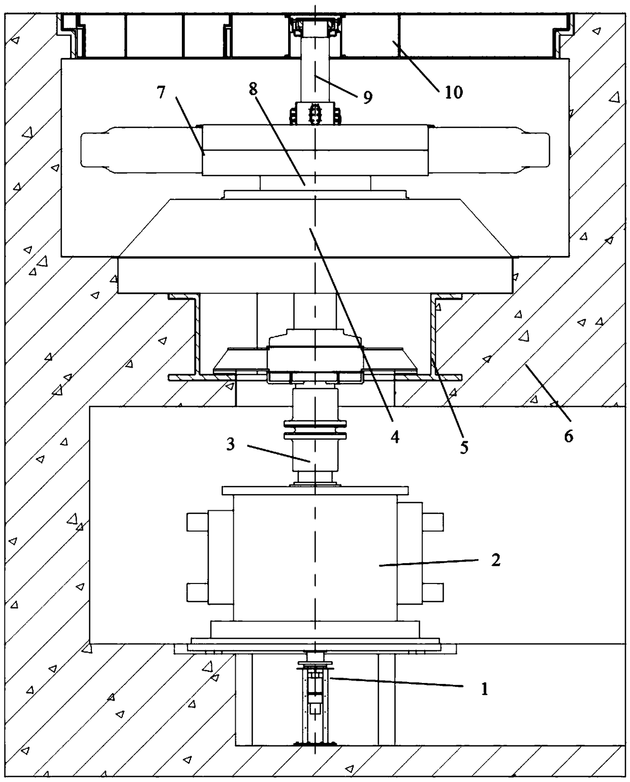
[0047] Example 1, such as figure 1 as shown,

[0048] A high-speed geotechnical centrifuge structure, installed in the concrete machine room 6, the concrete machine room 6 includes an underground negative floor and an underground negative second floor connected up and down, and the high-speed geotechnical centrifuge structure includes:

[0049] The main shaft 9 of the hollow structure;

[0050] The coupling 3, the motor 2, and the collector ring 1 for controlling the speed of the motor 2 are installed in the negative second floor of the concrete machine room 6; the motor 2 is installed in the concrete machine room 6 of the negative second floor underground, and the motor 2 The rotating shaft is connected to the main shaft 9 through the coupling 3; the collector ring 1 is installed at the lower part of the motor 2, and the water, electricity and air are transported into the main shaft 9 through the collector ring 1;

[0051] The rotating arm 7 and the middle transmission supp...

Embodiment 2

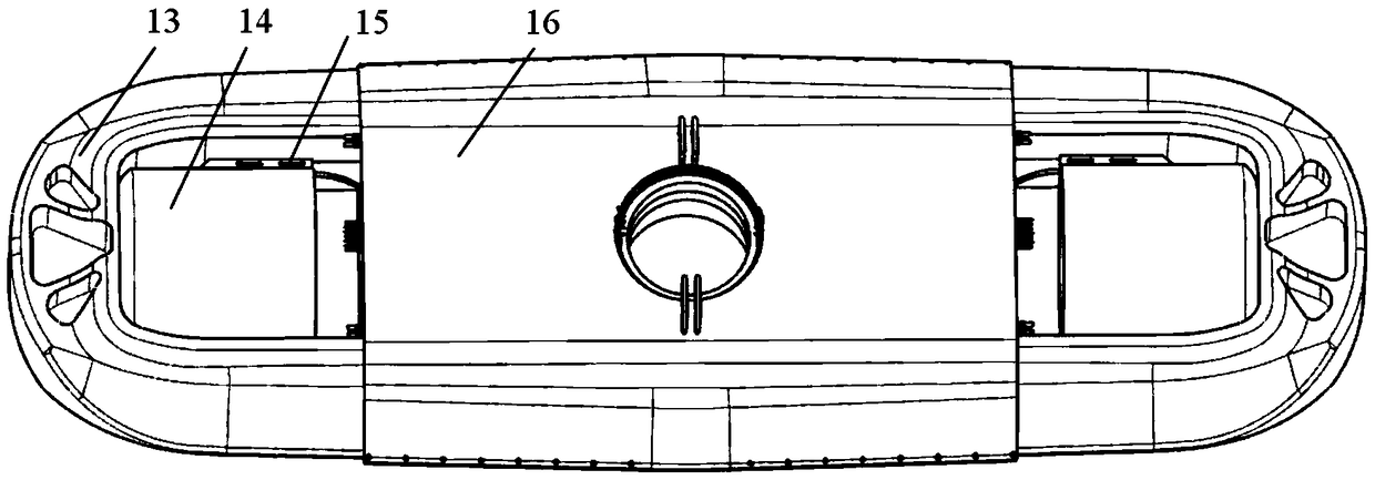
[0056] Example 2, such as image 3 as shown,

[0057] The difference between this embodiment and Embodiment 1 is that the rotating arm 7 includes:

[0058] Arm frame 13; the arm frame 13 is an integrally forged pocket beam structure;

[0059] pipeline support 16; the pipeline support 16 is set in the middle of the boom 13;

[0060] Slide rails 15; a group of slide rails 15 are arranged at both ends of the boom 13, and the installation direction of the slide rails 15 is perpendicular to the main shaft 9;

[0061] Hanging basket 14; the hanging basket 14 is slidably installed in the slide rail 15. When the high-speed geotechnical centrifuge rotates, the hanging basket 14 and the model in it will slide along the slide rail 15 under the action of centrifugal force, so that the bottom of the hanging basket 14 In contact with the boom 13.

[0062] The arm frame 13 adopts a pocket beam structure, which is integrally forged during manufacture, and can withstand a centrifugal force...

Embodiment 3

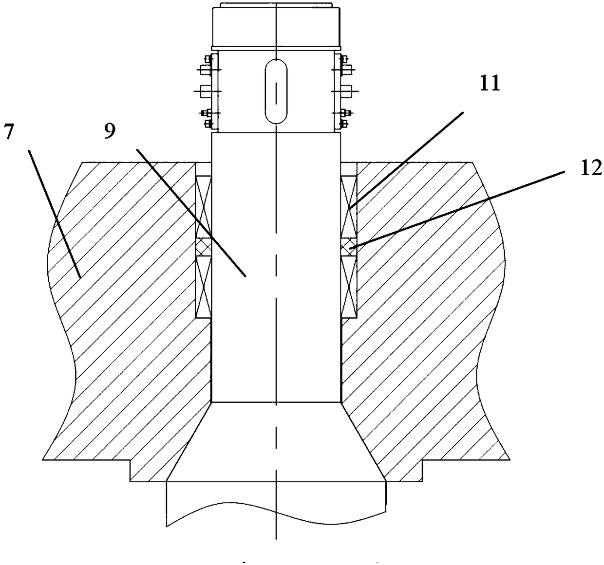
[0063] Example 3, such as Figure 4 as shown,

[0064] The difference between this embodiment and Embodiment 1 is that the structure of the high-speed geotechnical centrifuge also includes:

[0065] The upper transmission support, the upper transmission support includes an upper guide bearing seat 17 and an upper guide radial bearing 18; the upper guide bearing seat 17 is installed in the machine room cover plate 10, and the upper guide radial bearing 18 is set on the upper part of the main shaft 9 and installed on the On the upper guide bearing seat 17;

[0066] The lower transmission support; the lower transmission support includes the lower guide bearing seat 22 and the lower guide radial bearing 23, the lower guide bearing seat 22 is installed on the embedded part 5, the lower guide radial bearing 23 is set on the lower part of the main shaft 9, and is installed on the lower guide On the bearing seat 22;

[0067] The middle transmission support 4 includes a middle guide...


PUM


Abstract

The invention discloses a high-speed geotechnical centrifugal machine structure. By means of a symmetrical pocket-mounted integrally-forged rotating arm structure, horizontal sliding type symmetricalhanging basket structures and a transmission supporting structure which adopts three-fulcrum arrangement and the combination of hydrodynamic and hydrostatic sliding bearings and rolling bearings, thesituations that the capacity of a high-speed centrifugal machine can be equal to 1500gt, and the highest centrifugal acceleration can be equal to 1500g are ensured. In addition, by means of the symmetrical pocket-mounted integrally-forged rotating arm structure, the situation that the structure of the centrifugal machine can bear the load in the centrifugal field with the acceleration of being 1500g and the enormous centrifugal force generated by the structure of the centrifugal machine can be ensured; by means of the horizontal sliding type symmetrical hanging basket structures, the situations that the unbalanced force generated in the running process of the centrifugal machine is low, and the smooth running condition is met are ensured; and by means of the transmission supporting structure which adopts three-fulcrum arrangement and the combination of the hydrodynamic and hydrostatic sliding bearings and the rolling bearings, the enough supporting force is provided for the high-speedrunning of the centrifugal machine, the vibration is effectively controlled, the resonance which possibly happens between the centrifugal machine and the capital construction is avoided, and the situation that the acceleration of the centrifugal machine can be equal to 1500g is ensured.

Description

technical field [0001] The invention belongs to the technical field of centrifuges, and in particular relates to a high-speed geotechnical centrifuge structure. Background technique [0002] Since the world's first geotechnical centrifuge with a radius of 0.25m was born in Columbia University in the United States in 1931, after decades of development, more than 200 geotechnical centrifuges have been built around the world. By using the supergravity field generated by the high-speed rotation of the geotechnical centrifuge, the scale-down simulation problem of the geotechnical model can be effectively solved, and the model can be used to truly reproduce the prototype characteristics of civil engineering, which provides an effective means for studying actual civil engineering problems. [0003] At present, the centrifuge with the largest capacity built in the world is the 1144g·t centrifuge built by the French Actidyn Company for the Waterway Experiment Station (WES) of the US ...

Claims


Application Information

Patent Timeline
Patent Type & Authority Applications(China)
IPC IPC(8): B04B7/00B04B9/08
CPCB04B7/00B04B9/08
Inventor 冉光斌宋琼黎启胜许元恒陈良军洪建忠舒杨吕磊李心耀
Owner GENERAL ENG RES INST CHINA ACAD OF ENG PHYSICS
Learn More