Cable bending machine with high working efficiency

A technology of work efficiency and wire bending machine, applied in the direction of metal processing, manufacturing tools, metal processing equipment, etc., can solve the problems of increasing the bending workload of power cables, affecting the effect of cable bending, and low work efficiency, etc., to achieve The bending effect is good, the work efficiency is improved, and the labor load is reduced

Inactive Publication Date: 2019-02-22
STATE GRID ZHEJIANG NINGBO YINZHOU POWER SUPPLY LTD CO +2
View PDF6 Cites 0 Cited by
  • Summary
  • Abstract
  • Description
  • Claims
  • Application Information

AI Technical Summary

Problems solved by technology

In the traditional work experience, cable bending often requires the use of manual external force to bend the cable to change the path to meet the erection requirements, which increases the workload of the staff on the bending of the power cable
In the traditional bending of power cables, the operator often estimates the bending length and the radian of the curve in advance, and uses his hands and other parts of the body, or two or more people to forcefully bend the cable into a certain curvature, which is very laborious and will cause manual errors. , affecting the effect of cable bending, and the work efficiency is low, which cannot meet the existing requirements for quickly completing cable construction

Method used


Image

  • Cable bending machine with high working efficiency
  • Cable bending machine with high working efficiency
  • Cable bending machine with high working efficiency

Examples


Embodiment Construction

[0028] The present invention will be further described in detail below in conjunction with the accompanying drawings and specific embodiments.

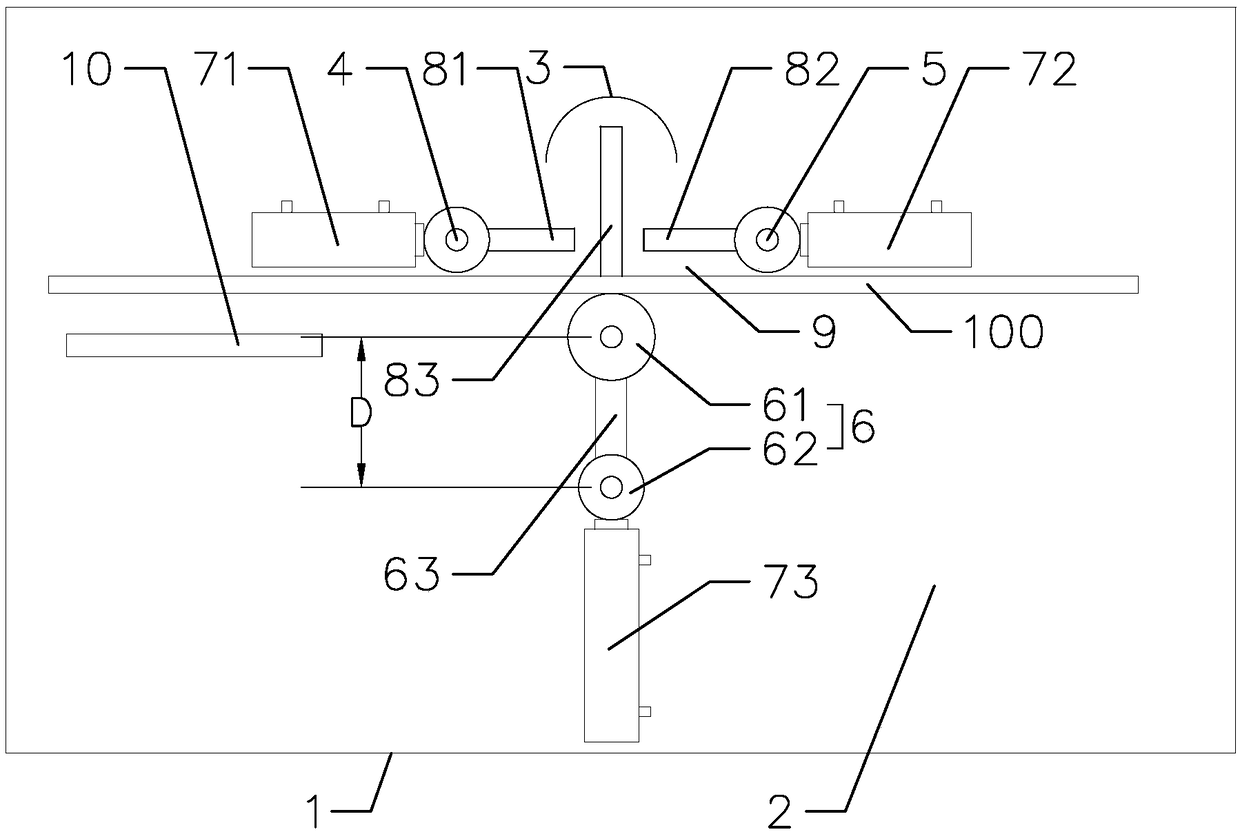
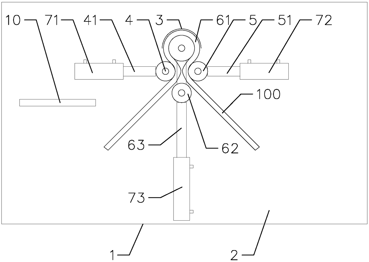
[0029] Such as Figures 1 to 4As shown, the present invention provides a cable bending machine with high working efficiency, which includes a cabinet 1, an operating table 2 arranged above the cabinet 1, a wire bending die 3 arranged on the operating table 2, and a first auxiliary wheel 4 , the second auxiliary wheel 5 and the driving wheel 6, the first auxiliary wheel 4 is driven by the first hydraulic cylinder 71, the second auxiliary wheel 5 is driven by the second hydraulic cylinder 72, the driving wheel 6 is driven by the third hydraulic cylinder 73, the first The hydraulic cylinder 71, the second hydraulic cylinder 72 and the third hydraulic cylinder 73 are all arranged in the cabinet 1, and the console 2 is provided with the first auxiliary wheel 4, the second auxiliary wheel 5 and the driving wheel 6 to reciprocate respectivel...


PUM


Abstract

The invention provides a cable bending machine with high working efficiency. The cable bending machine comprises a machine box, an operation table arranged above the machine box, a wire bending mold arranged on the operation table, a first auxiliary wheel, a second auxiliary wheel and a driving wheel, the first auxiliary wheel is driven by a first hydraulic air cylinder, the second auxiliary wheelis driven by a second hydraulic air cylinder, the driving wheel is driven by a third hydraulic air cylinder, the first hydraulic air cylinder, the second hydraulic air cylinder and the third hydraulic air cylinder are all arranged in the machine box, a first sliding groove, a second sliding groove and a third sliding groove which allow the first auxiliary wheel, the second auxiliary wheel and thedriving wheel to do reciprocating motion correspondingly are arranged on the operation table. The electric power is used for replacing manpower, so that the labor force is liberated, the labor amountof workers is reduced, compared with the manual work, the hydraulic air cylinders can be used for bending thicker and larger cable, so that the operation range is expanded, moreover, the cable bending work is standardized and procedural, then the working efficiency is improved, and the working process is accelerated.

Description

technical field [0001] The invention relates to the field of electric equipment, in particular to a cable bending machine with high working efficiency. Background technique [0002] Electricity is an indispensable part of people's life, production, travel, etc. In recent years, the country has vigorously developed and improved infrastructure equipment, and the power transmission system has also been greatly developed and improved. With the continuous pace of electrification construction in various regions of our country With the advancement of power supply enterprises and power customers, the requirements for the design, construction and maintenance of power facilities are getting higher and higher, the awareness of safe power supply and use is gradually increasing, and the use of power cables has gradually become popular. With the gradual increase in the electricity load of power customers, and the safety, reliability and practicability of power cables are gradually recogni...

Claims


Application Information

Patent Timeline
Patent Type & Authority Applications(China)
IPC IPC(8): B21F1/00B21C51/00
CPCB21C51/00B21F1/004
Inventor 吴高波潘沛峰杨志义李龙达诸晓颖张军郑坤力吴涛
Owner STATE GRID ZHEJIANG NINGBO YINZHOU POWER SUPPLY LTD CO
Why Eureka
Try Eureka