A steady frame for positioning in numerical control machining

A technology of center frame and fixed card, which is applied in metal processing equipment, metal processing mechanical parts, manufacturing tools, etc., can solve the problems of increasing part processing procedures and processing time, save processing time, solve circular runout, and reduce equipment. The effect of clip positioning time

Active Publication Date: 2020-12-18
浙江欧托电气有限公司
View PDF8 Cites 0 Cited by
  • Summary
  • Abstract
  • Description
  • Claims
  • Application Information

AI Technical Summary

Problems solved by technology

[0005] The invention provides a center frame for numerical control machining and positioning, which has the advantages of reducing the processing steps and processing time for slender shaft parts, and solves the problem that the existing center frame needs to center the parts to be processed before use. The surface of the frame support is polished, but this measure increases the processing steps and processing time of the part

Method used


Image

  • A steady frame for positioning in numerical control machining
  • A steady frame for positioning in numerical control machining
  • A steady frame for positioning in numerical control machining

Examples


Embodiment Construction

[0026] The following will clearly and completely describe the technical solutions in the embodiments of the present invention with reference to the accompanying drawings in the embodiments of the present invention. Obviously, the described embodiments are only some of the embodiments of the present invention, not all of them. Based on the embodiments of the present invention, all other embodiments obtained by persons of ordinary skill in the art without making creative efforts belong to the protection scope of the present invention.

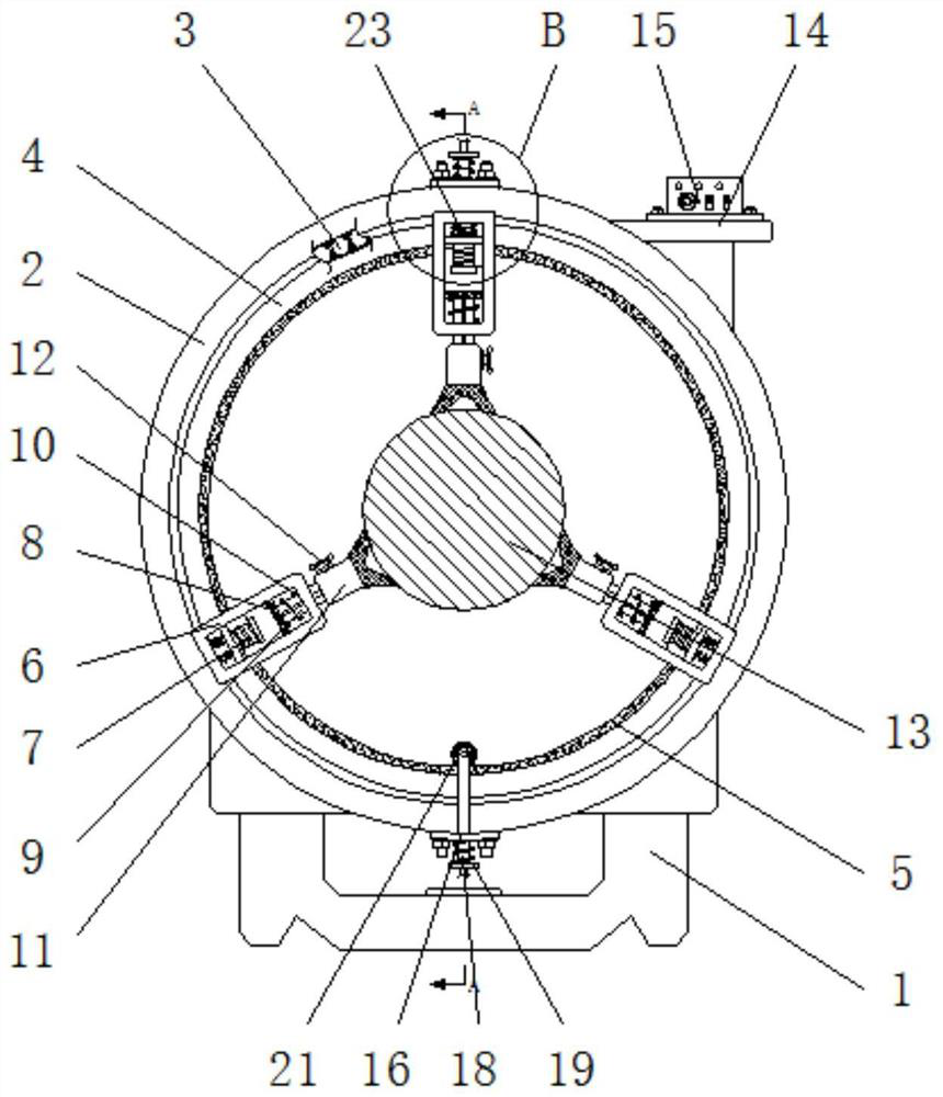
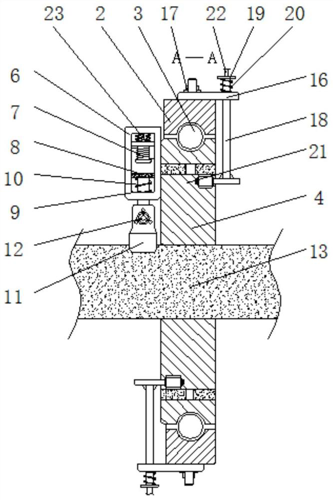
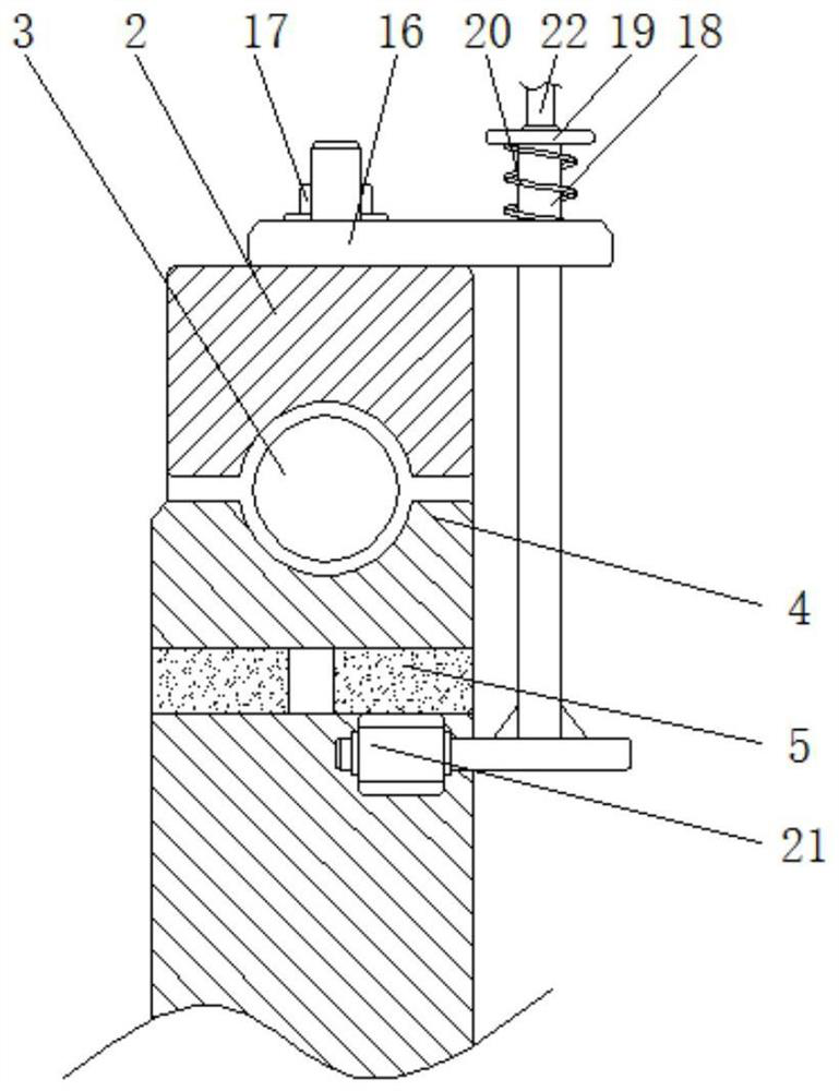
[0027] see Figure 1-6 , a center frame for numerical control machining positioning, including a base 1, a supporting outer ring 2 is fixedly installed on the top of the base 1, and supporting balls 3 are arranged inside the supporting outer ring 2, and the inner supporting outer ring 2 passes through the supporting balls 3 A supporting inner ring 4 is movable socketed, and the inner cavity of the supporting inner ring 4 is fixedly installed with...


PUM


Abstract

The invention relates to the technical field of intelligent numerical control equipment, and discloses a center frame for numerical control machining positioning. The center frame comprises a base; asupporting outer ring is fixedly installed at the top end of the base; the interior of the supporting outer ring is provided with a supporting ball and movably sleeved with a supporting inner ring through the supporting ball; and a conducting ring is fixedly installed in the inner cavity of the supporting inner ring. According to the center frame for numerical control machining positioning, by arranging three sets of electromagnets, when the center frame fixedly supports to-be-machined workpieces different in outer diameter, the magnitude and direction of the electric current of the center frame can be changed through an electric current controller only within the magnetic field intensity control range of the electromagnets, meanwhile, the problem that when an existing center frame fixedlysupports to-be-machined workpieces different in outer diameter, repeated positioning adjustment needs to be conducted on a threaded supporting claw of the center frame is solved, and the time, for clamping and positioning the to-be-machined workpieces different in outer diameter, of the center frame is effectively shortened.

Description

technical field [0001] The invention relates to the technical field of intelligent numerical control equipment, in particular to a steady frame for positioning in numerical control machining. Background technique [0002] The center frame is an indispensable auxiliary processing equipment when the machine tool is processing long shaft parts. When the machine tool is processing slender shaft parts, the center frame supports the middle part of the slender shaft parts to resist the The deflection of the center during processing is fixed. [0003] During the use of the existing center frame, the bolt claws are usually used to directly contact the surface of the part to be processed. There will be severe friction between the surface of the center frame and the relatively stationary bolt claws of the center frame, which will cause serious wear on the support surface of the part to be processed or the bolt claws of the center frame, which will lead to roundness of the high-speed r...

Claims


Application Information

Patent Timeline
Patent Type & Authority Patents(China)
IPC IPC(8): B23Q1/76
CPCB23Q1/763
Inventor 不公告发明人
Owner 浙江欧托电气有限公司
Why Eureka
Try Eureka