
A grinding positioning tool and v-groove grinding method for bending lower die

A technology for positioning tooling and positioning grooves, which is applied in the direction of grinding workpiece brackets, grinding machine parts, grinding/polishing equipment, etc., which can solve the problems of long processing time and cumbersome processing process, and achieve convenient processing and use. The method is simple and the relative position is accurate

Active Publication Date: 2020-07-24
无锡市求实特种模具有限公司
View PDF7 Cites 0 Cited by
  • Summary
  • Abstract
  • Description
  • Claims
  • Application Information

AI Technical Summary

Problems solved by technology

[0003] For the two V-grooves of the existing grinding and bending die, a grinding wheel grinder and manual grinding are required, and the two V-grooves are ground separately. Not only is the processing process cumbersome, the processing time is long, and it is difficult to ensure the centerline of the two V-grooves The technical problem that the dimensional tolerance of the distance meets the requirements, the invention provides a grinding and positioning tool for the lower bending die, and also provides a V-groove grinding method for the lower bending die, which can realize two V-groove Simultaneous grinding and forming, high processing efficiency and high precision

Method used


Image

  • A grinding positioning tool and v-groove grinding method for bending lower die
  • A grinding positioning tool and v-groove grinding method for bending lower die
  • A grinding positioning tool and v-groove grinding method for bending lower die

Examples


Embodiment Construction

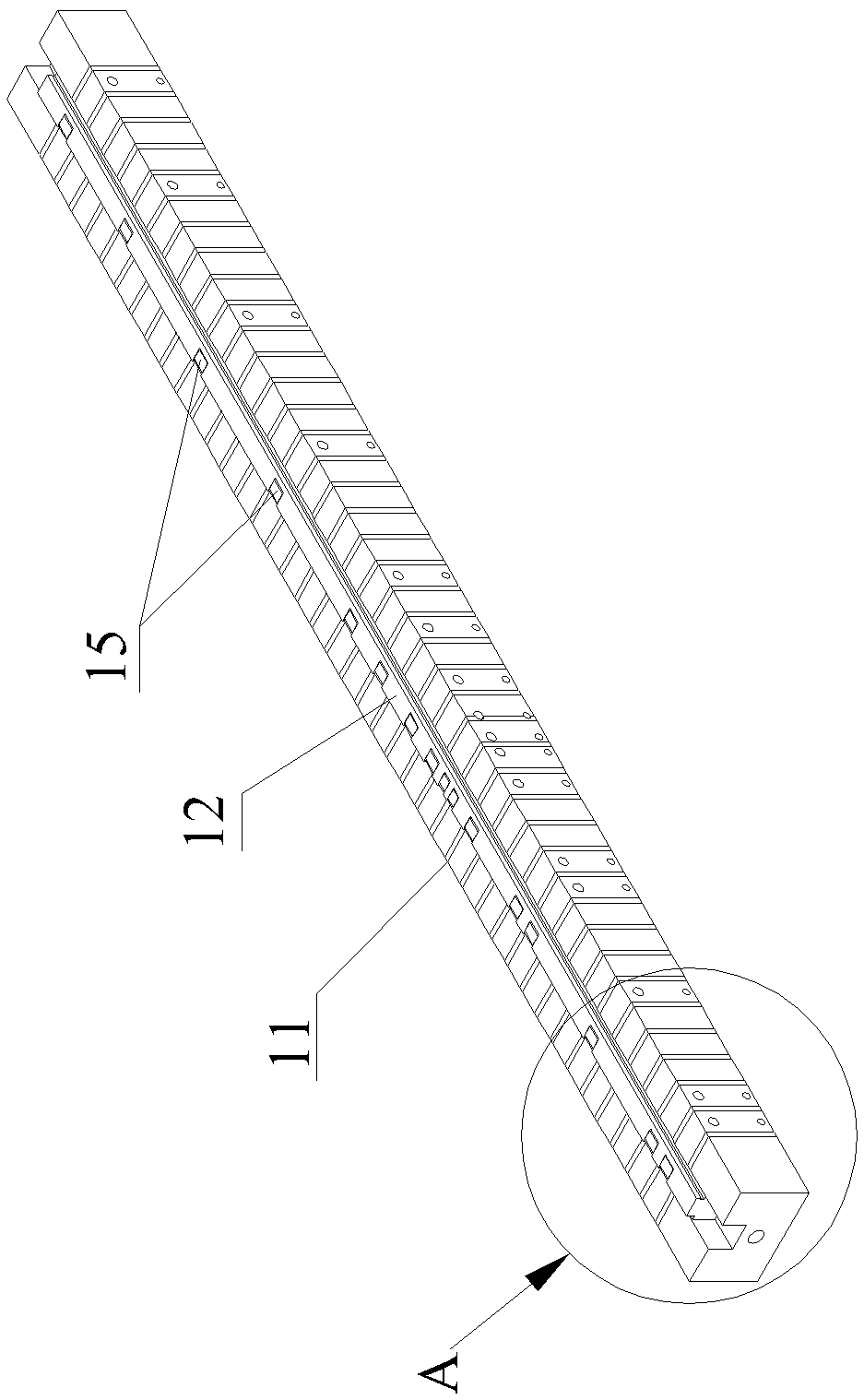
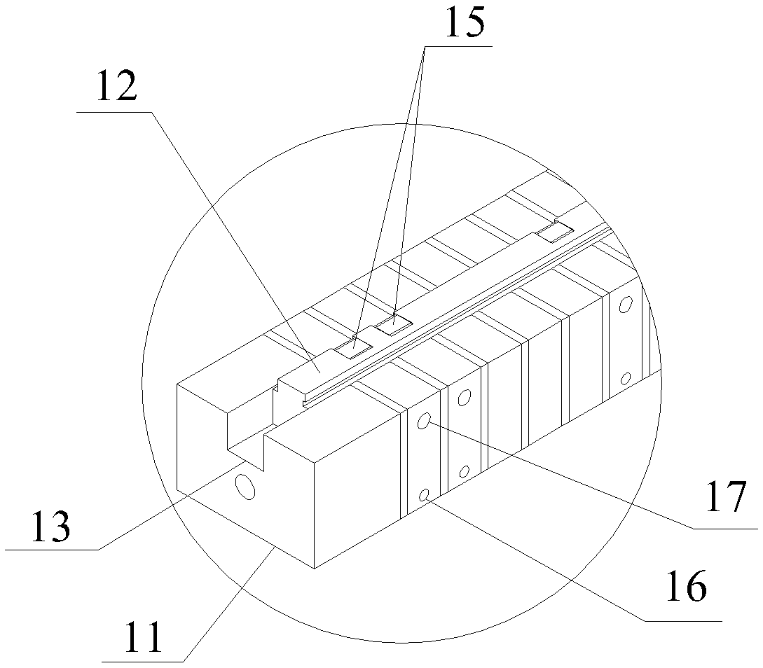
[0034] See Figure 2 to Figure 7 , a grinding and positioning tool for bending lower die of the present invention, which includes a magnetically conductive base 11 and a positioning block 12, the top surface of the magnetically conductive base is a horizontal positioning surface for supporting the bending lower die 1, and the magnetically conductive base A through groove 13 is opened on the top surface along the front and rear direction, and the positioning block 12 is fitted in the through groove 13 and its upper end protrudes from the through groove 13 and then inserted into the rectangular positioning groove 2 of the bending lower die 1. The upper end of the positioning block 12 is left The side is parallel to the left side of the rectangular positioning groove 2; the positioning block 12 and the magnetic base 11 are provided with mounting holes 14 that penetrate up and down, and the mounting holes 14 are provided with multiple mounting holes 14 along the magnetic base 11. ...


PUM


Abstract

The invention provides a grinding locating tool and V-groove grinding method for a bending lower die. By means of the grinding locating tool and V-groove grinding method for the bending lower die, theproblems that when two V grooves of an existing bending lower die are ground, grinding wheel grinding needs to be matched with manual grinding, the two V grooves are ground separately, the machiningprocess is complex, the machining time is long, and in addition, it is difficult to guarantee that the dimensional tolerance of the distance of central lines of the two V grooves meets the requirementcan be solved. The grinding locating tool comprises a magnetically-conductive base and locating blocks. The top face of the magnetically-conductive base is a horizontal locating face. The locating blocks are mounted in through grooves of the magnetically-conductive base in a matched and inserted manner, and the upper ends of the locating blocks extend out of the through grooves. The left side face of each locating block is parallel with the left side face of a corresponding rectangular locating groove of the bending lower die. Mounting holes which are through in the vertical direction are formed in the locating blocks and the magnetically-conductive base. Spring steel is mounted in the mounting holes in an inserted manner. The lower end of the spring steel is fixedly connected with the magnetically-conductive base. A tightly-jacking part is mounted at the position, at the left side of each piece of spring steel, on the magnetically-conductive base. Each tightly-pressing-against part can eject the upper end of the corresponding spring steel rightwards out of the corresponding through hole and enable the corresponding spring steel to tightly press out the right side face of the corresponding rectangular locating groove.

Description

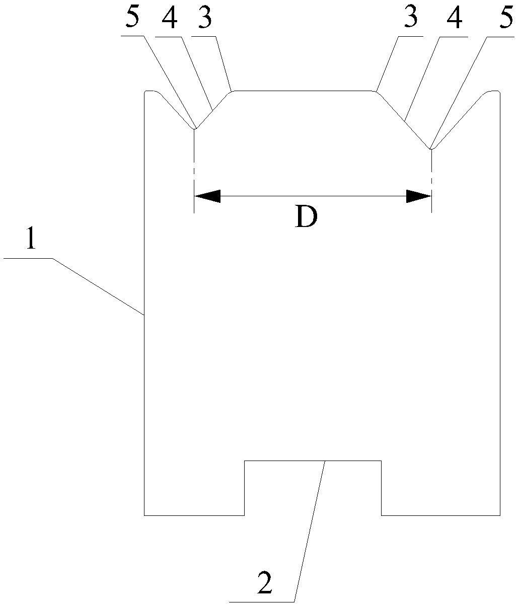
technical field [0001] The invention relates to the field of bending die processing, in particular to a grinding and positioning tool for a lower bending die and a V-groove grinding method. Background technique [0002] figure 1 It is a lower bending die with two V-grooves of different sizes, and a rectangular positioning groove 2 is processed on the bottom surface of the lower bending die 1 . Each V-groove has two notch R surfaces 3, two angled slopes 4 and a groove bottom R-surface 5. The distance D between the centerlines of the two V-grooves has a very small dimensional tolerance, making it difficult to process. The traditional V-groove processing method is to use a grinding wheel to grind the angle slopes of the two V-grooves respectively, and then manually polish the R-side of the notch and the R-side of the groove bottom of each V-groove. It is difficult to ensure that the dimensional tolerance of the distance D between the centerlines of the two V grooves meets the...

Claims


Application Information

Patent Timeline
Patent Type & Authority Patents(China)
IPC IPC(8): B24B19/20B24B19/02B24B41/06B24B53/14B24B1/00
CPCB24B1/00B24B19/02B24B19/20B24B41/06B24B53/14
Inventor 刘伟良王辉肖根法
Owner 无锡市求实特种模具有限公司
Learn More