Ferrying device for cleaning robot and cleaning robot system

A technology for cleaning robots and pushing devices, which is applied in the direction of manipulators, photovoltaic power generation, photovoltaic modules, etc., can solve the problems of position deviation, lack of limit devices, etc., and achieve the effects of easy control, cost saving, and simple structure

Pending Publication Date: 2019-02-22
郑州德瑞智能科技有限公司
View PDF1 Cites 8 Cited by
  • Summary
  • Abstract
  • Description
  • Claims
  • Application Information

AI Technical Summary

Problems solved by technology

The above-mentioned transfer vehicle travels through the walking wheels, which has special requirements on the working ground, and after walking to the preset position, it lacks the necessary limit device, and the position may be shifted

Method used


Image

  • Ferrying device for cleaning robot and cleaning robot system
  • Ferrying device for cleaning robot and cleaning robot system
  • Ferrying device for cleaning robot and cleaning robot system

Examples


Embodiment 1

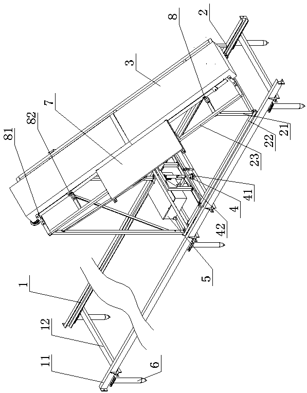
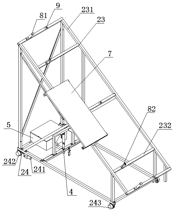
[0046] as attached Figure 1-4 As shown, the cleaning robot ferry device of the present invention includes an underframe, a support frame 21, a docking frame 23, a walking device 24, a ground track 1, a locking device 4, a transfer car body sensing device and a cleaning robot sensing device. The docking frame 23 is arranged on the top of the underframe 22 through the support frame 21, and the running gear 24 is arranged on the underframe 22. The above-mentioned underframe 22, the supporting frame 21, the docking frame 23 and the running gear 24 form the transfer car body 2; the ground track 1 Laid on the outside of the parallel photovoltaic panel arrays 13, for the traveling device 24 to move back and forth between the photovoltaic panel arrays 13; Whether to move to the corresponding photovoltaic panel array 13 ; the cleaning robot sensing device is arranged on the docking frame 23 for sensing whether the cleaning robot 3 moves to the docking frame 23 .

[0047] Wherein, the...

Embodiment 2

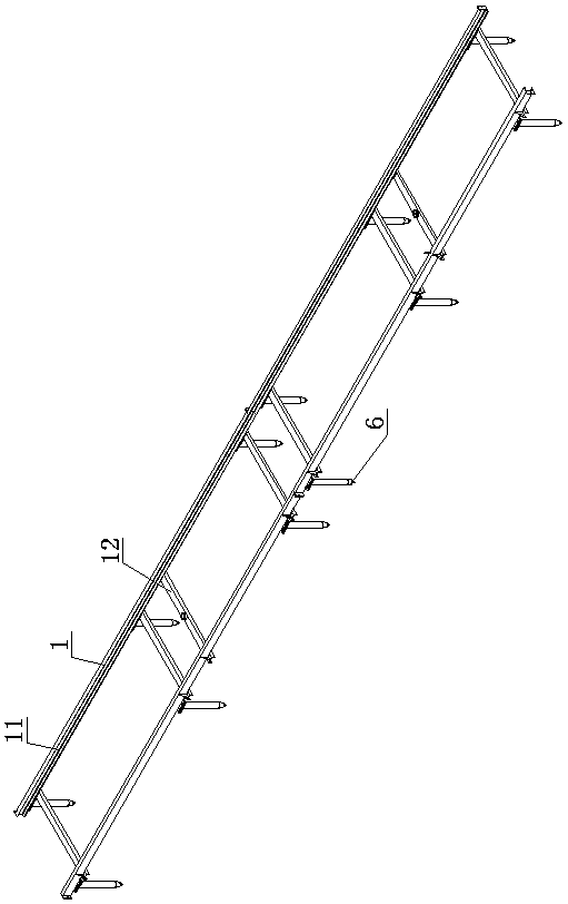
[0064] as attached Figure 5 As shown, this embodiment is a further improvement on the basis of Embodiment 1. The difference between this embodiment and Embodiment 1 is that it also includes a plurality of transition coupling frames 10, and the above multiple transition coupling frames 10 pass through the corresponding columns. Set above the ground track 1 in turn, each transition coupling frame 10 is arranged in parallel with the corresponding photovoltaic panel array 13 and connected to each other, and the docking frame 23 and the corresponding photovoltaic panel array 13 are connected to each other through the transition coupling frame 10. The cleaning robot 3 walks stably.

[0065] There is a one-to-one correspondence between the transition coupling frame 10 and the photovoltaic panel array 13 to be cleaned, and the number of transition coupling frames 10 is selected according to actual needs during installation. The transition coupling frame 10 is connected to the ground...

Embodiment 3

[0067] as attached Image 6 As shown, the cleaning robot system of the present invention includes the cleaning robot and the ferry device for the cleaning robot disclosed in Embodiment 2 of the embodiment.

[0068] The cleaning robot 3 includes a frame, a brush roller 31, a traveling mechanism, a driving device, a limit sensor 32, a speed sensor 39 and a robot electric control box 5, and a brush roller 31, which is rotatably arranged on A side end of the frame, the running mechanism is arranged on the frame, the driving device is arranged on the frame and is connected with the brush roller 31 and the running mechanism respectively, and the limit sensor 32 is arranged on a side end of the frame and connected with the brush On the same side of the roller 31, the speed sensor 39 is arranged on the traveling mechanism, and the robot electric control box 5 is arranged on the frame and is connected with the driving device, the limit sensor 32 and the speed sensor 39 respectively.

...


PUM


Abstract

The invention discloses a ferrying device for a cleaning robot and a cleaning robot system, and belongs to the field of photovoltaic board cleaning devices; and the problem of stable and safe reciprocating movement of the cleaning robot among photovoltaic board arrays is solved. The device comprises a transfer car body mainly consisting of a chassis, a support frame, a walking device and a berthing frame, and further comprises ground rails paved along the parallel photovoltaic board arrays, a locking device comprising a pin shaft, a pushing device and at least one pin hole, a transfer car bodyinduction device for inducing if the transfer car body moves to the corresponding photovoltaic board arrays, and a cleaning robot induction device for inducing if the cleaning robot is positioned onthe berthing frame, wherein the pin shaft and the pin hole are in plug-in fit through the pushing device to realize locking or unlocking of the transfer car body on the ground rails. The cleaning robot system comprises the cleaning robot and the ferrying device for the cleaning robot.

Description

technical field [0001] The invention relates to the field of photovoltaic panel cleaning devices, in particular to a ferry device for a cleaning robot and a cleaning robot system. Background technique [0002] Solar photovoltaic panels are installed outdoors and exposed to the natural environment continuously. The photovoltaic panels will absorb dust particles in the air. In addition, bird droppings, dust, fallen leaves, pollen, yellow sand and many other factors affect the efficiency of photovoltaic power generation modules to receive sunlight. In turn, the conversion efficiency of the power generation components is affected, resulting in a reduction in power generation. In particular, large-scale photovoltaic power plants are generally built in remote areas with low land use value such as desert saline-alkali land. The environment of these photovoltaic power plants is relatively harsh, and the sand and dust pollution is relatively serious, which affects the economic benefi...

Claims


Application Information

Patent Timeline
IPC IPC(8): B25J11/00B25J19/02B25J13/08H02S40/10
CPCH02S40/10B25J11/0085B25J13/08B25J13/088B25J19/02Y02E10/50
Inventor 苏冰曹国民
Owner 郑州德瑞智能科技有限公司
Why Eureka
Try Eureka