Supercharge Your Innovation With Domain-Expert AI Agents!

Rake receiver for reducing hardware consumption and improving search performance

A rake receiver and receiver technology, applied in the field of CDMA communication, can solve problems such as large hardware circuits

Inactive Publication Date: 2002-10-30
SAMSUNG ELECTRONICS CO LTD
View PDF4 Cites 0 Cited by
  • Summary
  • Abstract
  • Description
  • Claims
  • Application Information

AI Technical Summary

Problems solved by technology

[0006] However, since the rake receiver disclosed in the above-mentioned US Patent No. 5,237,586 uses an additional accumulator for each Walsh index, a large amount of hardware circuitry is required

Method used


Image

  • Rake receiver for reducing hardware consumption and improving search performance
  • Rake receiver for reducing hardware consumption and improving search performance
  • Rake receiver for reducing hardware consumption and improving search performance

Examples


Embodiment Construction

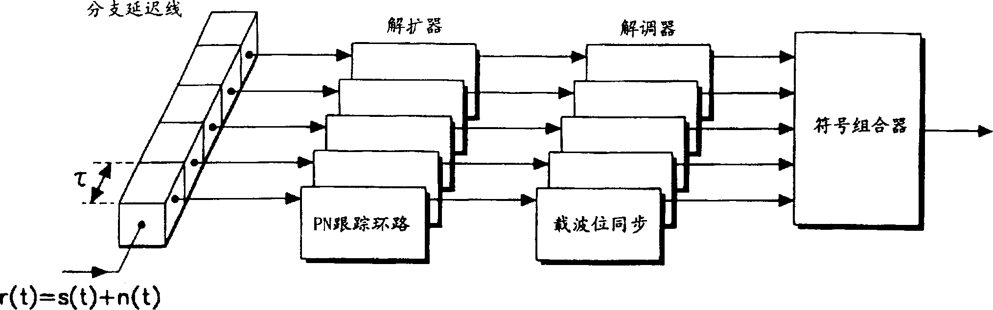
[0015] In the present invention, the Rake receiver and its symbol combiner for processing signal distortion caused by multipath in a wireless environment are improved. When the information sent from the transmitter reaches the Rake receiver through different paths due to various reasons such as weather, terrain, etc., the receiver compensates for the different arrival delay time. For this reason, the Rake receiver not only receives the strongest signal but also receives various path signals with different delay times and adds these signals to each other, thereby improving the receiving sensitivity.

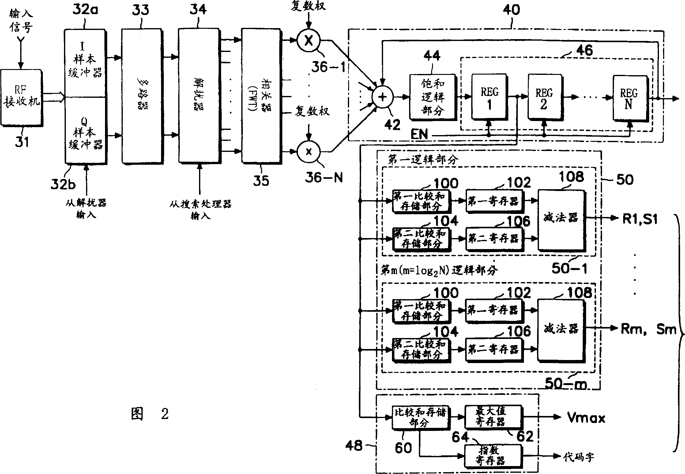
[0016] Fig. 2 is a functional block diagram of a rake receiver according to the present invention. In FIG. 2, RF (radio frequency) receiver 31, I (in-phase) sample buffer 32a, Q (quadrature) sample buffer 32b, multiplexer 33, descrambler 34, correlator 35, complex multiplier 36 -1 to 36-N have the same structure as the corresponding frame shown in FIG. 11 of the aforementioned U.S. Pa...


PUM


Abstract

A rake receiver for receiving a data signal transmitted from a transmitter in a spread spectrum communication system, comprising: a symbol combiner for adding output values ​​of Walsh exponents sequentially generated from a correlator to an N-stage shift In the value generated by the last stage of the register, and shift the accumulated value output by the rake receiver; the first decision logic part is used to determine the maximum value and generate the Walsh exponent corresponding to the determined maximum value as a code word; and A second decision logic section for searching and subtracting the value output by the symbol combiner and generating possible values ​​of the codeword according to the state of each bit of the corresponding index.

Description

Technical field [0001] The present invention relates to a CDMA (Code Division Multiple Access: Code Division Multiple Access) communication technology in a cellular wireless telephone communication system, in particular to a method for correlating received signal samples with despreading code sequences to determine received data Sequence of RAKE receivers. Background technique [0002] In a spread spectrum system, if a spread spectrum signal passes through a multipath fading channel, the received signal assumes a format obtained by superimposing multiple path components each having a different amplitude and phase with each other. In this case, because the power components of other multipath signals are lost, and only the main channel signal with the strongest power is received, it is undesirable from the perspective of efficiency. [0003] In the Rake receiver, multiple receivers in parallel format figure 1 Shown are used in order to jointly participate in...

Claims


Application Information

Patent Timeline
IPC IPC(8): H04B7/02H04B1/06H04B1/709H04B1/7115H04L27/30
CPCH04B1/709H04B1/7115H04B1/06
Inventor 李志远
Owner SAMSUNG ELECTRONICS CO LTD
Features
  • R&D
  • Intellectual Property
  • Life Sciences
  • Materials
  • Tech Scout
  • Unparalleled Data Quality
  • Higher Quality Content
  • 60% Fewer Hallucinations
Learn More