Pile foundation structure breakwater with energy dissipation chamber

A technology for energy dissipation chambers and breakwaters, which is applied in the direction of breakwaters, embankments, jetties, etc. It can solve the problems that the wave baffle is not a hollow structure, the elevation of the top of the structure increases, and occupies a large area of ​​the sea area, so as to achieve low construction difficulty and reduce the impact force , The effect of occupying a small area of ​​sea area

Inactive Publication Date: 2019-02-22
CHINA COMM CONSTR FIRST HARBOR CONSULTANTS
View PDF10 Cites 3 Cited by
  • Summary
  • Abstract
  • Description
  • Claims
  • Application Information

AI Technical Summary

Problems solved by technology

The disadvantage is that the slope structure occupies a larger sea area than the vertical structure
The patent No. CN201010580554 claims a kind of air-permeable breakwater containing inner and outer wave baffles and an upper wave wall. The disadvantage is that the wave baffle is not a hollow structure. great force
The patent No. CN201120565865 and the patent No. CN96105834 respectively advocate a kind of air-permeable breakwater. The former basically has no wave dissipation ability and all rely on wave blocking to realize the anti-wave function. The structure itself will block the waves, which will inevitably lead to an increase in the elevation of the top of the structure and an increase in investment

Method used


Image

  • Pile foundation structure breakwater with energy dissipation chamber
  • Pile foundation structure breakwater with energy dissipation chamber
  • Pile foundation structure breakwater with energy dissipation chamber

Examples


Embodiment

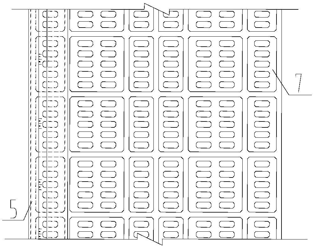
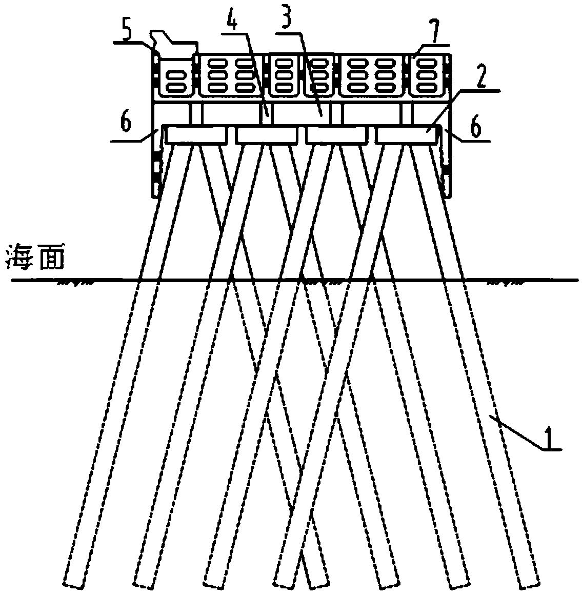
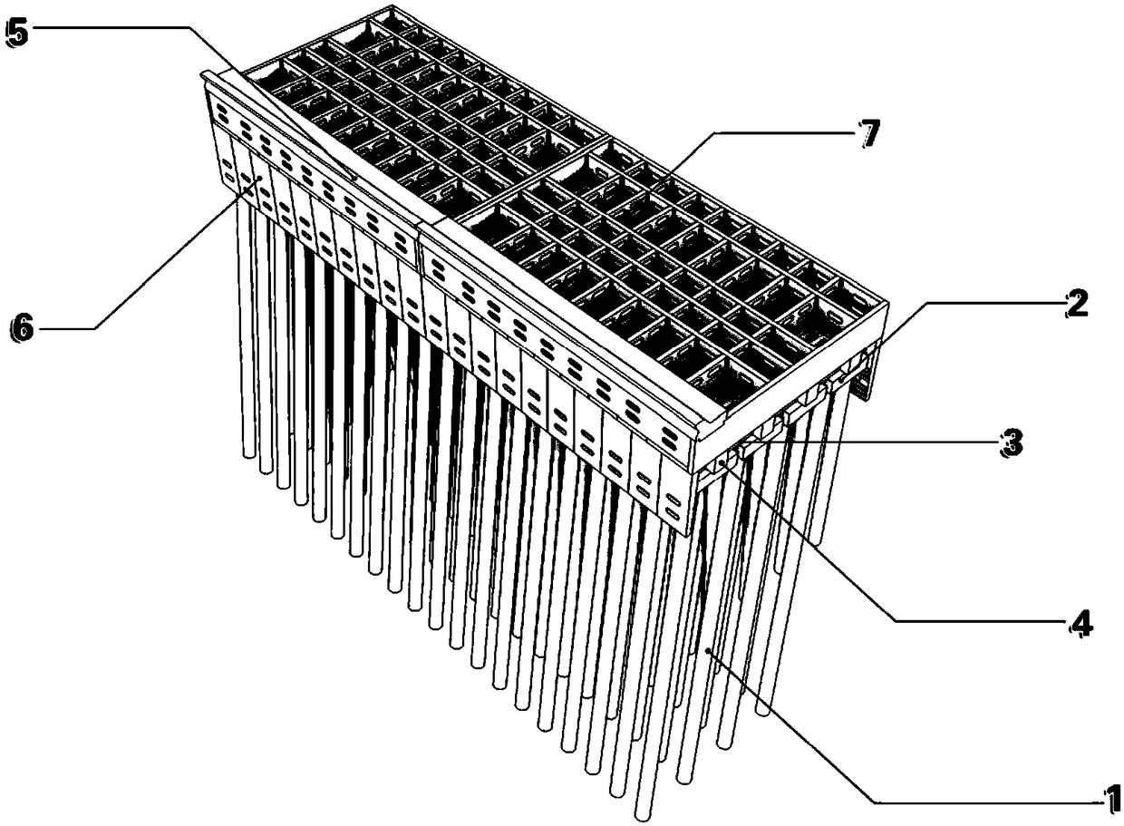
[0017] Such as figure 1 and figure 2 The shown pile foundation structure breakwater with energy dissipation chamber is composed of pile foundation 1, pile foundation cap 2, beam 3, longitudinal beam 4, wave retaining wall 5, wave retaining plate 6, and energy dissipation chamber 7. Pile body 1 is a steel pipe pile with a diameter of 1.5m, a wall thickness of 16mm, a pile length of 35m, a pile top elevation of -2.5m, and a slope of the pile body of 4:1; the cap is 1.5m thick, prefabricated, and cast-in-place at the connection with the pile; The height of the prefabricated transverse and longitudinal beams is 2m, and they are lapped vertically and horizontally on the caps, and then cast-in-place, and the transverse and longitudinal beams, caps and piles are connected into a whole through the reserved steel bars on the caps; the wave baffles are prefabricated, similar to the installation method of the longitudinal beams ;The upper part of the transverse and longitudinal beams i...


PUM


Abstract

The invention provides a pile foundation structure breakwater with an energy dissipating chamber. The pile foundation structure breakwater with the energy dissipating chamber comprises pile foundations, a pile foundation cap, crossbeams, longitudinal beams, and the energy dissipation chamber, wherein a plurality of pile foundations are arranged under the pile foundation cap; the upper portion of the pile foundation is in lap joint mode with the is crossed crossbeams and longitudinal beams which can support the energy dissipating chamber; a wave-proof wall is arranged on the upper sea side of the energy dissipating chamber; manger boards are correspondingly arranged on the sea side and the harbor side; and the peripheries and a base plate of the energy dissipating chamber are all in a hollow-out design. The pile foundation structure breakwater with the energy dissipating chamber has the advantages of reducing the crosswise wave effect, and the downward impact of the lengthways wave andthe upward uplift pressure through the clear design of the manger boards, the gap between the pile foundations, the gap formed by the lap joint of the crossbeams and the longitudinal beams, and the clear design of the peripheries and the base plate of the energy dissipation chamber, thereby possessing a good wave breaking effect which is namely an energy dissipation effect. The pile foundation structure breakwater with the energy dissipating chamber also has the advantages of low construction difficulty, and high degree assembling; meanwhile the breakwater is environmental friendly and the engineering cost can be saved.

Description

technical field [0001] The invention belongs to the field of port construction, and in particular relates to a pile foundation structure breakwater with an energy dissipation chamber. Background technique [0002] Breakwater is an important hydraulic structure in port and coastal engineering. Its main function is to prevent waves from invading the port waters, affecting port operations, and damaging various facilities in the port. The structural types of breakwaters at home and abroad include slope type, vertical type and mixed type. Various structural types have their advantages and disadvantages and applicable conditions. ① Slope-type breakwaters are generally built by throwing stones or various forms of concrete blocks; there are also ripraps at the embankment core, and the surface layer is protected by heavy concrete blocks. Slope-type breakwaters are generally suitable for places with small water depth, poor foundation and abundant stone sources. If concrete blocks a...

Claims


Application Information

Patent Timeline
Patent Type & Authority Applications(China)
IPC IPC(8): E02B3/06
CPCE02B3/066Y02A10/11
Inventor 吴波季则舟魏芸李斌李超冯璐胡珅榕侯伟
Owner CHINA COMM CONSTR FIRST HARBOR CONSULTANTS
Why Eureka
Try Eureka