
Running control method of cold water unit or heat pump unit

A technology for heat pump units and chillers, used in refrigerators, refrigeration components, refrigeration and liquefaction, etc., can solve the problems of low outlet water temperature, affecting the normal operation of the unit, and freezing of pipelines, and achieve the effect of meeting customer needs.

Active Publication Date: 2019-02-22
SHANDONG PEIRCE
View PDF6 Cites 4 Cited by
  • Summary
  • Abstract
  • Description
  • Claims
  • Application Information

AI Technical Summary

Problems solved by technology

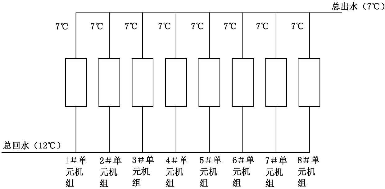
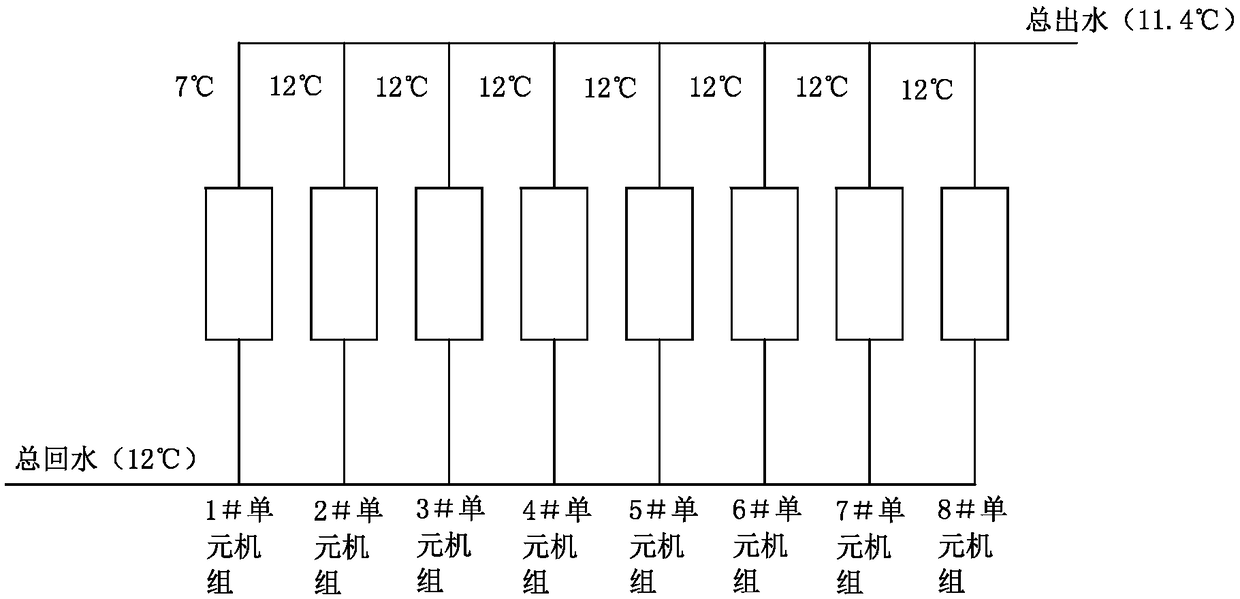
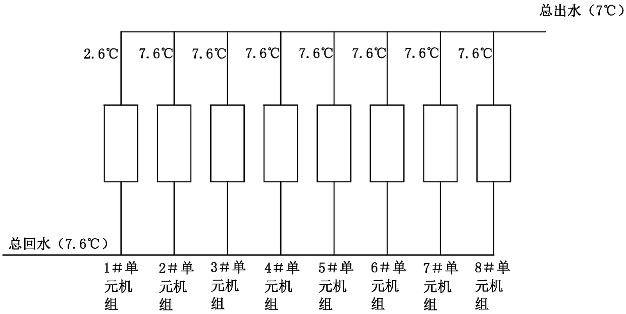
Only 1# unit unit runs at full load during load hours, see image 3 , the outlet water temperature is too low (the outlet water temperature of 1# unit unit is 2.6°C < 3°C); for the above problems, the general solution is to increase the total outlet water temperature, but this method will not meet the user’s 7°C outlet water demand. Or lower the alarm value of the outlet water temperature, but if the outlet water temperature is too low, it may cause the pipeline to freeze and affect the subsequent normal operation of the unit

Method used


Image

  • Running control method of cold water unit or heat pump unit
  • Running control method of cold water unit or heat pump unit
  • Running control method of cold water unit or heat pump unit

Examples


Embodiment 1

[0048] Each chiller or heat pump unit includes 8 unit units, and the 8 unit units operate in parallel, each unit unit includes 4 compressors, and the running time of the 8 unit units is T, T=2; the 8 unit units are respectively They are 1# unit unit, 2# unit unit, 3# unit unit, 4# unit unit, 5# unit unit, 6# unit unit, 7# unit unit and 8# unit unit.

[0049] The operation control method of the present invention is used to alternately load and unload the compressors in the eight unit units one by one to achieve balanced and decentralized operation. The operation control method includes the following steps:

[0050] S1. Calculate the least common multiple of 2, 3, and 4 that can be selected by compressors as the total load of the unit unit; calculate the ratio of the total load of the unit unit to the number of compressors in the unit unit, and calculate it as the load of each compressor; calculate the unit The product of the load of each compressor in the unit and the operating...

Embodiment 2

[0089] The concept of the second embodiment is basically the same as that of the first embodiment. The only difference is that the number of unit units, the number of compressors in the unit unit and the setting of the unit running time are different. The following will only describe this embodiment for the differences.

[0090] The chiller unit or heat pump unit includes 4 unit units, the 4 unit units are 1# unit unit, 2# unit unit, 3# unit unit, 4# unit unit; 1# unit unit includes 3 compressors, each compressor Machine load = 4; 2# unit unit includes 2 compressors, each compressor unit load = 6; 3# unit unit and 4# unit unit both include 4 compressors, each compressor unit load = 3, and 1 The running time of #unit unit is T=2, the running time of 2# unit unit is T+1=3, the running time of 3# unit unit is T+3=5, the running time of 4# unit unit is T+2 = 4; The sequence of 4 unit units is set in advance as 1# unit unit, 2# unit unit, 3# unit unit and 4# unit unit. In order to...


PUM


Abstract

The invention discloses an operation control method of a cold water unit or a heat pump unit, the units comprises a plurality of unit plants which are connected in parallel and contain two to four compressors. The operation control method comprises the following steps of acquiring the total load values of the unit plants, the load values of each compressor and the operation load values of the unitplants, preset sorting the sequence of the unit plants, and load or load-reducing conditions are preset. During operation, the unit plants operation load values are re-sequenced according to preset sorting, then selecting unit plants which are equal to the operation load values of the sequencing the first unit plant, re-sequencing is carried out according to the load values of each compressor, aunit which is equal to the load of the first each compressor at the moment is selected, then sorting is carried out according to the running time, at the moment, the first unit plant is ordered to beloaded or unloaded targets under the corresponding sequencing. According to the operation control method, the compressors of the unit plants can be alternatively loaded or unloaded one by one so as toachieve balanced dispersion operation, so that the water outlet temperature is prevented from being too low, and the requirements of customers are met.

Description

technical field [0001] The invention belongs to the technical field of operation control of water chillers or heat pump units, and in particular relates to an operation control method of water chillers or heat pump units suitable for refrigeration, water outlet control mode, and multi-unit joint control. Background technique [0002] Common chillers or heat pump units adopt a multi-unit joint control strategy, that is, the chiller includes multiple unit units operating in parallel, and each unit unit usually only has a single cooling mode, mainly including 2 to 4 compressors, condensers, The throttling parts and evaporator, the refrigerant flows in one direction in the evaporator and condenser; or the heat pump unit includes multiple unit units operating in parallel, and each unit unit mainly includes 2 to 4 compressors, condensers, and economizers. Flow components, evaporator and four-way reversing valve, through the switching of the four-way reversing valve to realize the ...

Claims


Application Information

Patent Timeline
IPC IPC(8): F25B49/02
CPCF25B49/02
Inventor 张欢
Owner SHANDONG PEIRCE
Learn More