An energy-saving electrical fire detector dedicated to electrical equipment

A technology for electrical fire and electrical equipment, applied to fire alarms, instruments, alarms, etc., can solve the problems of few functions, complex structure of electrical fire detectors, lack of display brightness, etc., and achieve the effect of improving practicability

Active Publication Date: 2021-07-09
徐州明盛高新科技有限公司
View PDF26 Cites 0 Cited by
  • Summary
  • Abstract
  • Description
  • Claims
  • Application Information

AI Technical Summary

Problems solved by technology

[0004] The purpose of the present invention is to provide a dedicated energy-saving electrical fire detector for electrical equipment to solve the problem that the structure of the energy-saving electrical fire detector dedicated to electrical equipment is more complicated, the function is less, and it does not have the function of automatically adjusting the brightness of the display screen according to the intensity of external sunlight. energy-saving electrical fire detector

Method used


Image

  • An energy-saving electrical fire detector dedicated to electrical equipment
  • An energy-saving electrical fire detector dedicated to electrical equipment
  • An energy-saving electrical fire detector dedicated to electrical equipment

Examples


Embodiment 1

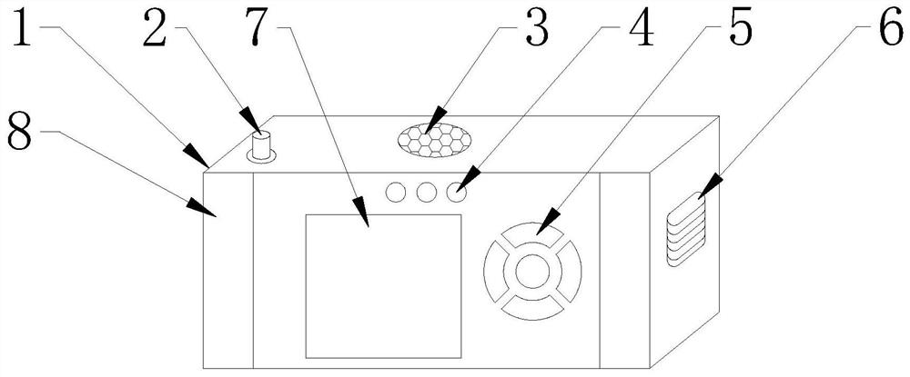
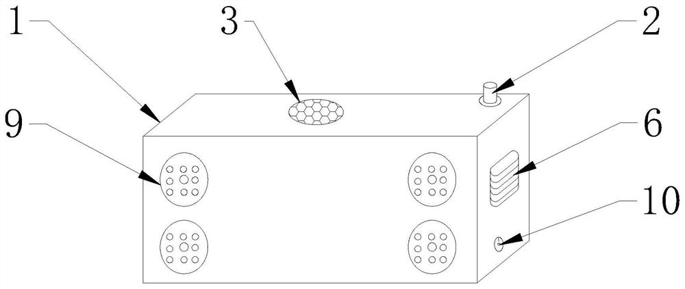
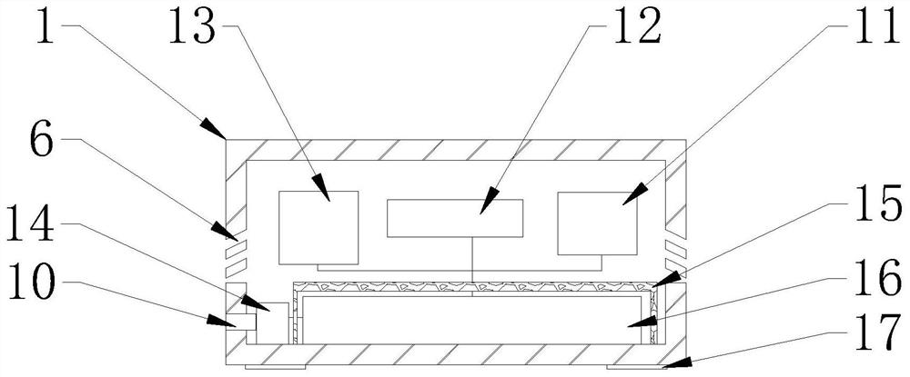
[0028] Embodiment one, with reference to Figure 1-4 , an energy-saving electrical fire detector dedicated to electrical equipment, comprising a device casing 1, an alarm speaker 3 is embedded and connected to the middle position of the top of the device casing 1, a device switch 2 is fixedly connected to the left side of the front top of the device casing 1, and the device casing The left and right ends of the front of the device 1 are fixedly connected with a photosensitive sensor 8, the top of the front of the device housing 1 is embedded with a device status indicator 4, and the middle part of the front of the device housing 1 is embedded with a smart display 7. The front left of the device housing 1 The control button 5 is inlaid and connected to the middle position of the side, the device fixing suction cup 9 is fixedly connected to the four corners of the back of the device casing 1, the device charging hole 10 is embedded and fixedly connected to the bottom right side o...

Embodiment 2

[0033] Embodiment two, refer to figure 1 , the photosensitive sensor 8 is provided with two places, is respectively arranged on the left and right sides of the front of the device casing 1, and the energy-saving electrical fire detector dedicated to the existing electrical equipment is set to be equipped with a smart display 7, and the smart display 7 It will be convenient for the staff to observe and debug the energy-saving electrical fire detector dedicated to electrical equipment when the brightness is increased when there are staff operating, but when the intelligent display screen 7 is at the highest brightness when no staff is operating, it consumes a lot of power, and the photosensitive The sensor 8 can detect the brightness of the surrounding environment of the energy-saving electrical fire detector dedicated to electrical equipment, and then adjust the brightness of the smart display 7 to reduce the power consumption of the energy-saving electrical fire detector dedica...

Embodiment 3

[0034] Embodiment three, with reference to Figure 4 , the branch supervisor 901 is provided with two places, which are respectively arranged in the middle position of the upper part of the device fixing suction cup 9 and the lower part of the device fixing suction cup 9. When the device is fixed, the air in the suction cup 9 will be evacuated through the air opening 903, so that the energy-saving electrical fire detector dedicated to electrical equipment can be firmly adsorbed on the electric cabinet, and the remaining current conducting wire 902 will touch the electric cabinet. , the energy-saving electrical fire detector dedicated to electrical equipment will work normally, and the branch supervisor 901 is responsible for connecting the air receiving and releasing port 903 inside the fixed suction cup 9 of the device to transmit the air, ensuring the energy-saving electrical fire detector dedicated to electrical equipment. The detector can be firmly fixed on the electric ca...


PUM


Abstract

The invention discloses an energy-saving electrical fire detector dedicated to electrical equipment, which comprises a device casing, an alarm speaker is embedded and connected to the middle position of the top end of the device casing, photosensitive sensors are fixedly connected to the left and right ends of the front of the device casing, and the device casing The top of the front is embedded with a device status indicator light, the middle part of the front of the device shell is embedded with a smart display, and the left side of the inner bottom of the device shell is fixedly connected with a power supply voltage regulator. When the energy-saving electrical fire detector is charged, the current flowing into the energy-saving electrical fire detector dedicated to electrical equipment is processed to ensure that the current flowing into the power supply of the device is a stable current to avoid voltage and current instability during charging. The device power supply in the energy-saving electrical fire detector dedicated to electrical equipment will be damaged, and the practicability of the energy-saving electrical fire detector dedicated to electrical equipment will be improved.

Description

technical field [0001] The invention belongs to the technical field of electrical equipment, in particular to an energy-saving electrical fire detector dedicated to electrical equipment. Background technique [0002] Electrical fire detectors are also called residual current fire detectors, which are used to detect the leakage current in electrical circuits to determine the possibility of fire. Residual current electrical fire monitoring detectors are mainly divided into: non-independent detectors, It can detect residual current and output an alarm signal when the residual current reaches the set value. It must be used in conjunction with monitoring equipment. The simplest non-independent detector is only composed of a residual current transformer and a micropower relay. The perfect non-independent detector has the functions of alarm current setting, address coding, etc., and is powered in a centralized manner. Since there is no sound and light alarm, it is not easy to find ...

Claims


Application Information

Patent Timeline
Patent Type & Authority Patents(China)
IPC IPC(8): G08B17/00
CPCG08B17/00
Inventor 董名球杨毅黄罗通郑永国董佳欣
Owner 徐州明盛高新科技有限公司
Why Eureka
Try Eureka