New energy automobile battery protective device

A battery protection device, new energy vehicle technology, applied in the direction of batteries, battery pack components, circuits, etc., can solve problems such as poor safety, explosion, and severe battery combustion, and achieve the effect of preventing combustion

Inactive Publication Date: 2019-02-22
赵鹏凯
View PDF8 Cites 14 Cited by
  • Summary
  • Abstract
  • Description
  • Claims
  • Application Information

AI Technical Summary

Problems solved by technology

[0002] With the continuous mining of non-renewable energy, fossil energy is getting less and less, so new energy vehicles are developing day by day. New energy vehicles are generally powered by lithium batteries, and due to the requirements of battery life, lithium batteries installed in cars are generally The number is large, the volume is large, and the battery will generate a lot of heat when it supplies power. Therefore, it is necessary to effectively cool the battery. The existing method generally cools the battery by continuously passing cold air into the battery box, but in case of In the event of a traffic accident, since the battery will rupture or even burn due to extrusion and deformation, the cooling air introduced at this time will help the combustion to a certain extent, and the batteries on traditional new energy vehicles are generally not equipped with active and timely fire extinguishing and battery isolation. When the car collides, the battery is very easy to burst due to the collision, causing the battery to burn violently or even explode, and then a more serious secondary accident occurs, which is less safe.

Method used


Image

  • New energy automobile battery protective device
  • New energy automobile battery protective device
  • New energy automobile battery protective device

Examples


Embodiment Construction

[0020] The following will clearly and completely describe the technical solutions in the embodiments of the present invention with reference to the accompanying drawings in the embodiments of the present invention. Obviously, the described embodiments are only some, not all, embodiments of the present invention.

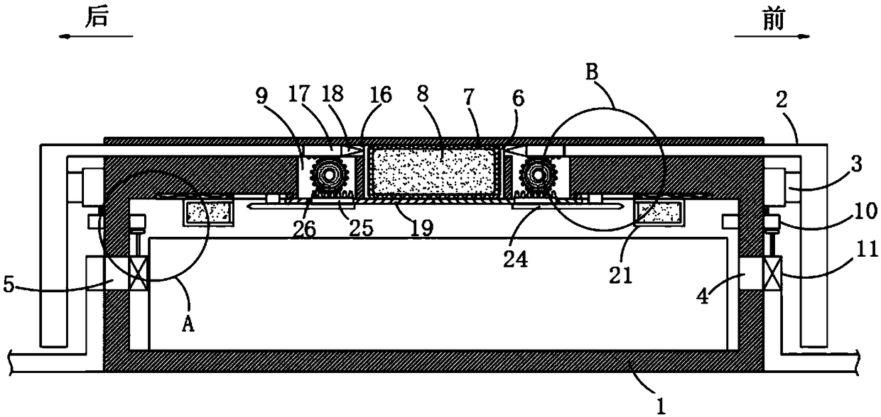
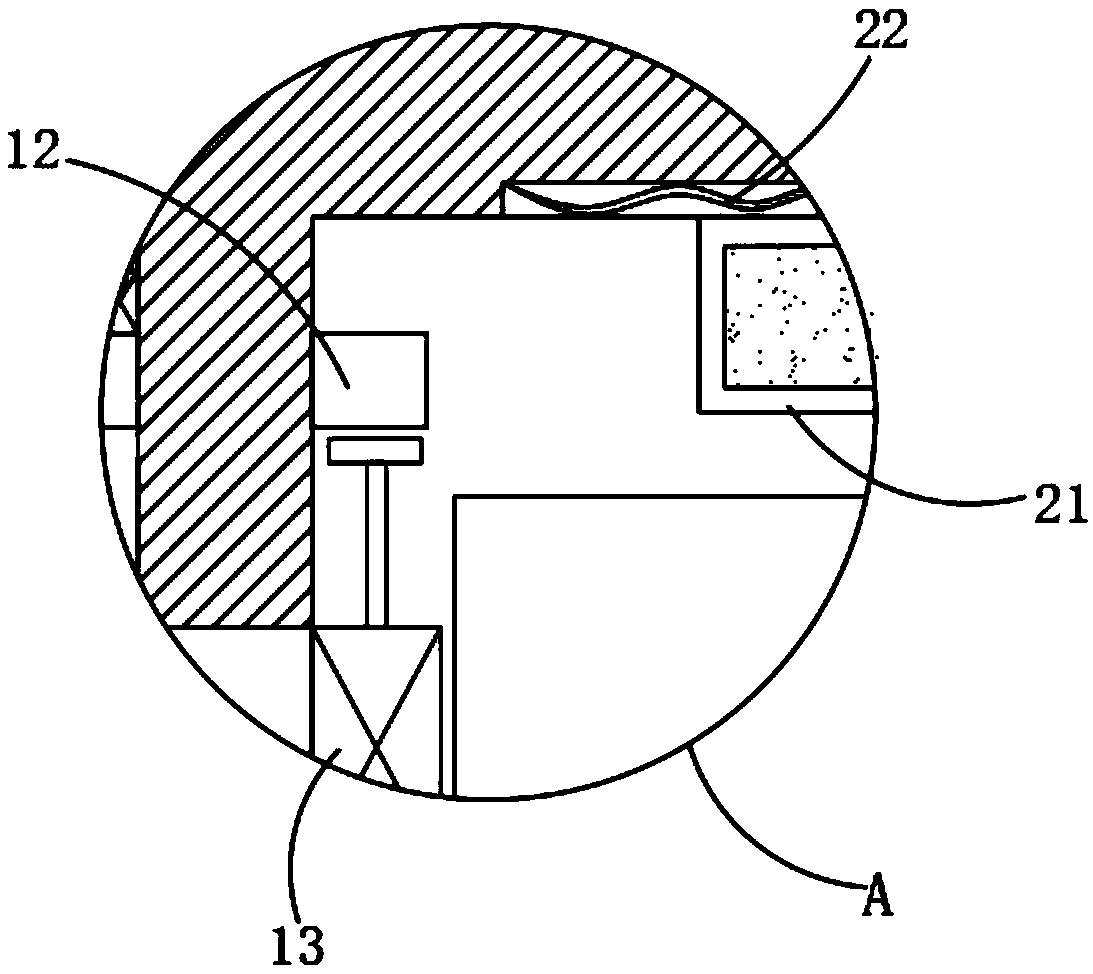
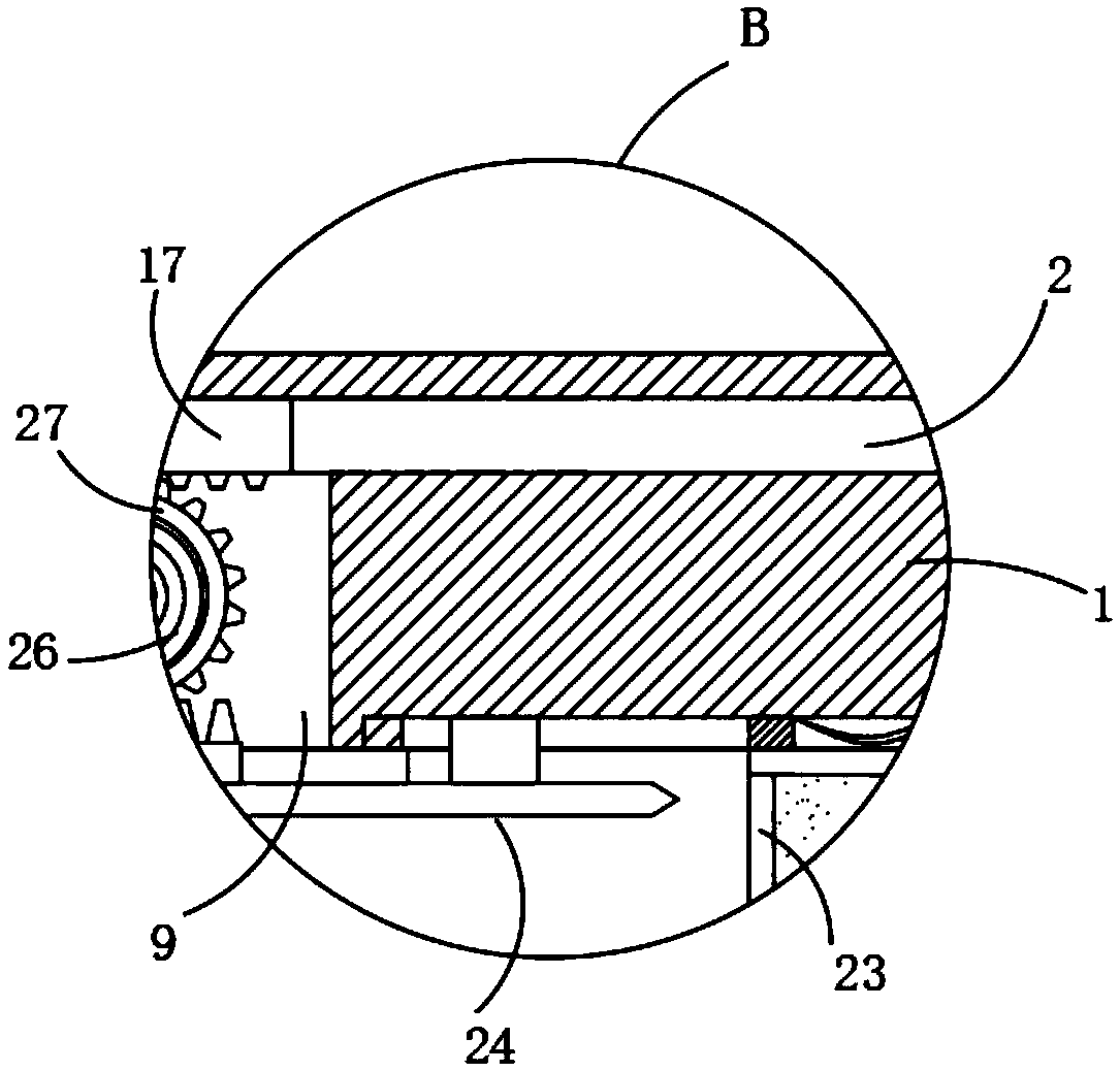
[0021] refer to Figure 1-5 , a new energy vehicle battery protection device, including a battery box 1 for placing batteries and a protective mechanism located outside the battery box 1, the protective mechanism includes two L-shaped plates 2 located on the front and rear sides of the battery box 1, and L The vertical part of the template 2 is connected with the battery box 1 through a buffer cylinder 3, and the front and rear ends of the battery box 1 are respectively provided with an air inlet 4 and an air outlet 5, and the air inlet 4 can be connected with a cold air inlet pipe, so that The cold air enters the battery box 1, cools the battery and discharges it th...


PUM


Abstract

The invention discloses a new energy automobile battery protective device. The new energy automobile battery protective device comprises a battery holder for placing a battery and a protective mechanism located outside the battery holder, wherein the protective mechanism comprises two L-shaped plates which are respectively located at the front side and rear side of the battery holder; the verticalparts of the L-shaped plates are connected to the battery holder through buffering air cylinders; an air inlet and an air outlet are respectively formed in the front end and rear end of the battery holder; a front blocking mechanism for blocking the air inlet is arranged on the side wall of the battery holder; the buffering air cylinders drive the front blocking mechanism to move; a rear blockingmechanism for blocking the air outlet is arranged on the inner wall of the battery holder; and a storage tank is arranged on the inner top wall of the battery holder. When an automobile is collided,the new energy automobile battery protective device timely sprays dry powder into the battery holder; if the automobile meets the open fire, the new energy automobile battery protective device can generate carbon dioxide by decomposing to play a role in flame retardant, and further reduce the oxygen content in the battery holder, can seal and isolate the battery holder and further prevents a battery from burning.

Description

technical field [0001] The invention relates to the technical field of new energy vehicles, in particular to a new energy vehicle battery protection device. Background technique [0002] With the continuous mining of non-renewable energy, fossil energy is getting less and less, so new energy vehicles are developing day by day. New energy vehicles are generally powered by lithium batteries, and due to the requirements of battery life, lithium batteries installed in cars are generally The number is large, the volume is large, and the battery will generate a lot of heat when it supplies power. Therefore, it is necessary to effectively cool the battery. The existing method generally cools the battery by continuously passing cold air into the battery box, but in case of In the event of a traffic accident, since the battery will rupture or even burn due to extrusion and deformation, the cooling air introduced at this time will help the combustion to a certain extent, and the batte...

Claims


Application Information

Patent Timeline
Patent Type & Authority Applications(China)
IPC IPC(8): H01M2/10A62C3/16H01M50/249
CPCA62C3/16H01M2200/00H01M50/20Y02E60/10
Inventor 杨志刚
Owner 赵鹏凯
Why Eureka
Try Eureka