TSPC flip-flop with set function

A trigger and function technology, applied in the direction of pulse generation, electrical components, generation of electrical pulses, etc., can solve the problems of a large number of MOS transistors and a large layout area, and achieve a reduction in the layout area, a small number, and an increase in the operating frequency range. Effect

Active Publication Date: 2019-02-22
SHANGHAI HUAHONG GRACE SEMICON MFG CORP
View PDF4 Cites 5 Cited by
  • Summary
  • Abstract
  • Description
  • Claims
  • Application Information

AI Technical Summary

Problems solved by technology

[0004] The disadvantages of this flip-flop are: the number of MOS transistors used is large, and the layout area occupied is large

Method used


Image

  • TSPC flip-flop with set function
  • TSPC flip-flop with set function
  • TSPC flip-flop with set function

Examples


Embodiment Construction

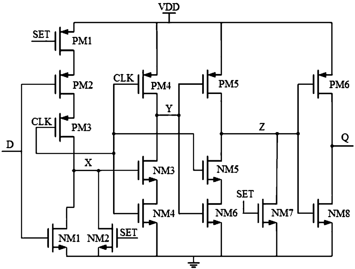
[0021] figure 2 Shown is a schematic diagram of an embodiment of a TSPC flip-flop with a set function in the present invention. In this embodiment, the TSPC flip-flop with set function includes: six PMOS transistors PM1-PM6 and eight NMOS transistors NM1-NM8.

[0022] The sources of the PMOS transistors PM1, PM4-PM6 are connected to the power supply voltage VDD terminal. The PMOS transistors PM2, PM3 and the NMOS transistor NM1 are serially connected in sequence between the drain of the PMOS transistor PM1 and the ground. The node where the drain of the PMOS transistor PM3 is connected to the drain of the NMOS transistor NM1 is denoted as X. The gate of the PMOS transistor PM1 receives a set signal SET. The gate of the NMOS transistor NM1 and the gate of the PMOS transistor PM2 serve as the input terminal D of the flip-flop.

[0023] The drain of the NMOS transistor NM2 is connected to the node X, its source is grounded, and a set signal SET is input to its gate.

[0024...


PUM


Abstract

The invention discloses a TSPC flip-flop with a set function, comprising: six PMOS transistors and eight NMOS transistors, wherein the drain of the seventh NMOS transistor is connected to a node Z, the source thereof is grounded, and the gate thereof inputs a signal SET. The seventh NMOS transistor functions both as a circuit set function device and as leakage compensation, and plays an importantrole in increasing the operating frequency range of the circuit. The TSPC flip-flop can increase the operating frequency range of the trigger and reduce the occupied layout area.

Description

technical field [0001] The invention relates to the field of semiconductor integrated circuits, in particular to a TSPC (true single-phase clock control register) flip-flop with a setting function. Background technique [0002] As an indispensable sequential logic structure in standard cells, D flip-flops are widely used in various designs. [0003] The existing traditional D flip-flop with set function such as figure 1 As shown, it consists of four MOS transistors, seven inverters and two NAND gates. [0004] The disadvantages of this flip-flop are: the number of MOS transistors used is large, and the layout area occupied is large. The operating frequency range is 1Hz to 2GHz. [0005] How to design a D flip-flop with a small layout area and a wide operating frequency range is a goal that has been pursued in digital circuit design. Contents of the invention [0006] The technical problem to be solved by the present invention is to provide a TSPC flip-flop with a setti...

Claims


Application Information

Patent Timeline
Patent Type & Authority Applications(China)
IPC IPC(8): H03K3/356
CPCH03K3/356
Inventor 曹亚历邵博闻
Owner SHANGHAI HUAHONG GRACE SEMICON MFG CORP
Why Eureka
Try Eureka