
Vacuum suction cup pressure-suction auxiliary device replacing vacuum pump outside CNC machining machine

A vacuum suction cup and auxiliary device technology, which is applied to metal processing mechanical parts, positioning devices, metal processing equipment, etc., can solve the problems of high price and large volume, and achieve the effect of simple structure, small volume and production cost saving.

Pending Publication Date: 2019-02-26
CHENGDU KAITIAN ELECTRONICS
View PDF0 Cites 0 Cited by
  • Summary
  • Abstract
  • Description
  • Claims
  • Application Information

AI Technical Summary

Problems solved by technology

[0004] The purpose of the present invention is to provide a vacuum pump with small volume, fast and convenient installation and disassembly, free from price and quantity restrictions of the vacuum pump, and save energy Production cost, can replace the CNC machining vacuum sucker suction pressure auxiliary device that realizes the function of the vacuum pump

Method used


Image

  • Vacuum suction cup pressure-suction auxiliary device replacing vacuum pump outside CNC machining machine
  • Vacuum suction cup pressure-suction auxiliary device replacing vacuum pump outside CNC machining machine
  • Vacuum suction cup pressure-suction auxiliary device replacing vacuum pump outside CNC machining machine

Examples


Embodiment Construction

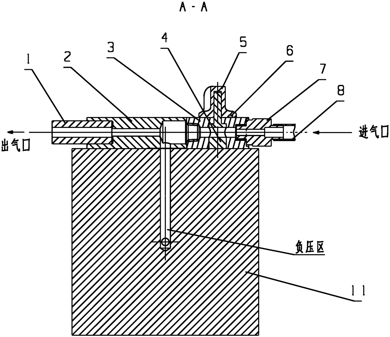
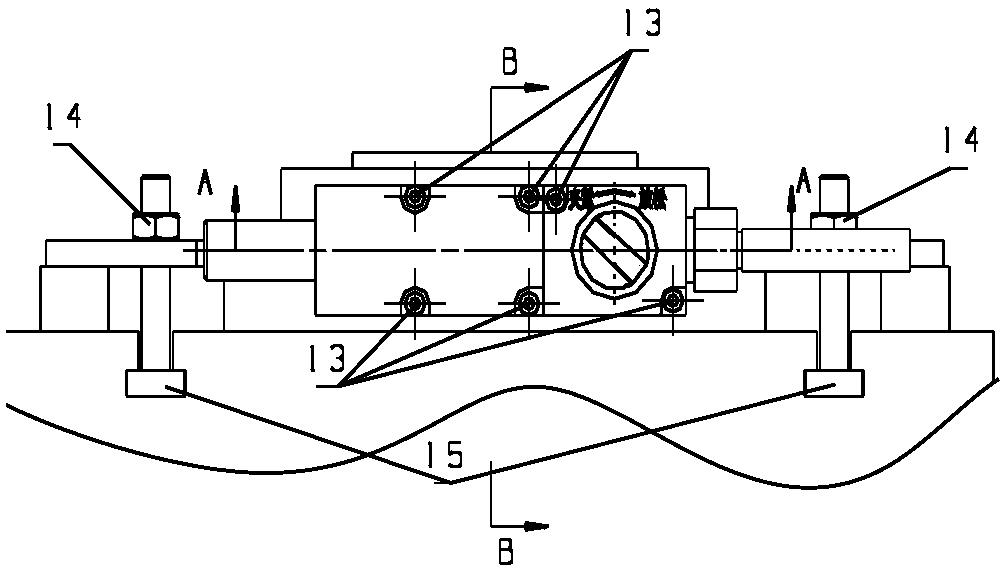
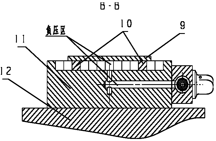
[0019] refer to figure 1 . The lower part of the valve core 4 of the suction device for the vacuum suction cup is fitted with the steering body 3 through the round hole, and is screwed to the vacuum suction cup 11 of the CNC machining center equipment accessory through the hexagon socket bolt 13, and the steering body 3 is equipped with a stop pin 6 Sliding arc-shaped groove, the knob 5 is clearance-fitted with the upper part of the valve core 4 through the rectangular groove, and has an interference fit with the stop pin 6. By rotating the knob 5, the stop pin 6 is driven to slide along the arc-shaped pin groove of the steering body 3 to be in "clamping" Or at the "relaxed" position mark, realize the state that the valve core 4 is connected or blocked with compressed air. One side of the steering body 3 is equipped with a threaded connection nozzle 7, and after the intake pipe 8 is pressed into the nozzle 7, the compressed air enters the air passage of the whole device throu...


PUM


Abstract

The invention discloses a vacuum suction cup pressure-suction auxiliary device replacing a vacuum pump outside a CNC machining machine and is aimed at providing a pressure-suction auxiliary device which is quick and convenient to install and disassemble, saves production cost, and can replace the function of the vacuum pump. The invention is achieved by the following technical solution: the upperpart of the valve core is matched with a knob through a rectangular groove; the knob drives the stop pin to slide along the curved pin groove of the steering body by the rotary motion; as that compressed air communicates through the spool with the nozzle, the air flow path of the steer body and the valve body, a negative pressure zone is formed between the vacuum chuck attached to the machining cent equipment and the workpiece to be clamped, and a pressure difference is formed between the negative pressure zone and the atmospheric pressure on the surface of the workpiece to be clamped. The clamped workpiece is completely attached to the vacuum cup after being subjected to force, and the valve core communicates or blocks the compressed air, so as to realize the clamping or relaxing state ofthe clamped workpiece, and further realize the quick clamping, machining and dismantling of the clamped workpiece.

Description

technical field [0001] The invention relates to a suction device for a vacuum suction cup attached to a numerical control machining center, in particular to a device for realizing fast installation, clamping and processing of thin plate parts. Background technique [0002] When the CNC machining center processes thin plate parts, in order to reduce the deformation of the plate parts during processing and improve the quality of the parts, the attached vacuum suction cup is usually used to clamp the processed parts. The uniform fluidity of vacuum chuck tooling gas is mainly affected by the consistency of pressure. If the gas fluidity of each cavity is inconsistent, that is, the vacuum degree of each cavity is different, it will cause uneven pressure on the parts, which may seriously deform the parts. distortion. In order to solve such problems, it is necessary to slot longitudinally and horizontally on each cavity of the vacuum chuck tooling. In order to make the gas between ...

Claims


Application Information

Patent Timeline
Patent Type & Authority Applications(China)
IPC IPC(8): B23Q3/08
CPCB23Q3/065B23Q3/088
Inventor 王礼凤胡永明樊虎
Owner CHENGDU KAITIAN ELECTRONICS
Learn More