
Oiling equipment for chemical fiber silk production

A technology of chemical fiber yarn and equipment, applied in the field of oiling equipment for chemical fiber yarn production, can solve the problems of poor chemical fiber oil leakage effect, easy wear of roller shaft, poor oiling effect of chemical fiber yarn, etc., and achieves safe and convenient use. , The effect of reducing the contact area and reducing the loss

Inactive Publication Date: 2019-02-26
长兴一盛纺织有限公司
View PDF8 Cites 0 Cited by
  • Summary
  • Abstract
  • Description
  • Claims
  • Application Information

AI Technical Summary

Problems solved by technology

[0004] The present invention provides an oiling equipment for the production of chemical fiber yarns, which can effectively solve the problem that when the equipment proposed in the above-mentioned background technology is prone to wear and tear during use, the connecting shaft and the sealing cover produce gaps, and the chemical fiber oil inside the oil roller is reduced, The oil leakage effect of chemical fiber becomes worse, and the oiling effect of chemical fiber yarn becomes worse

Method used

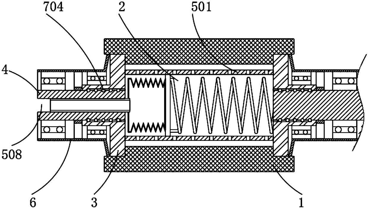
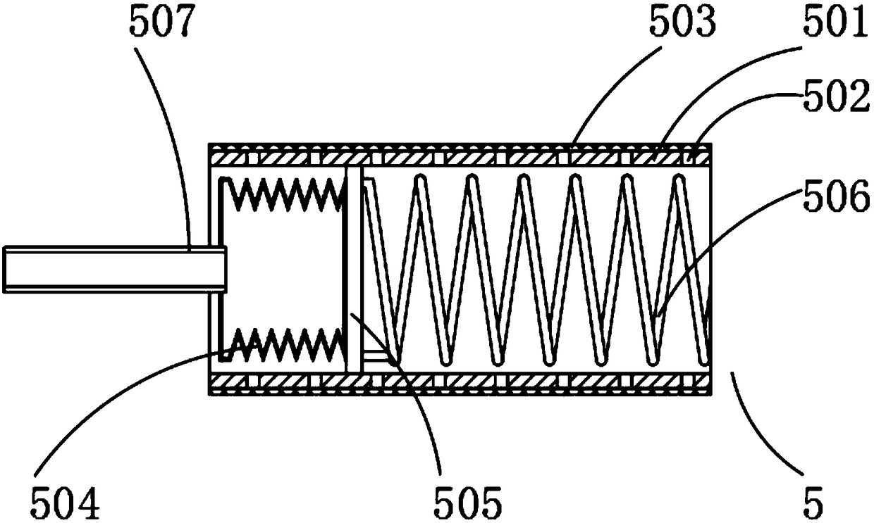
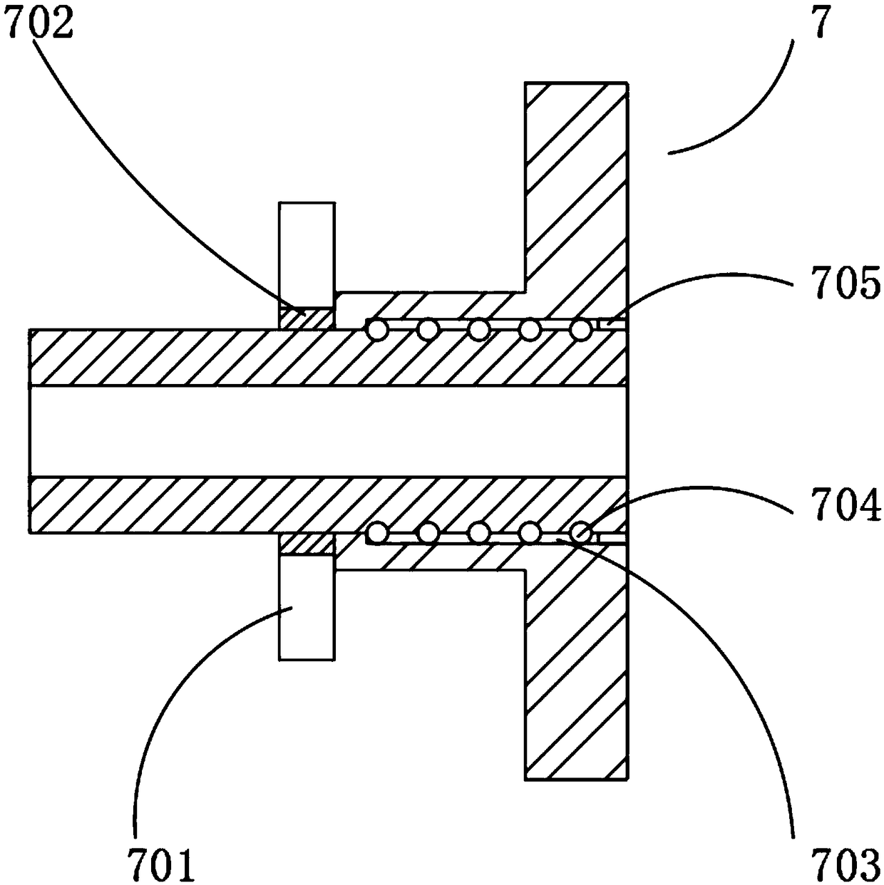

Image

  • Oiling equipment for chemical fiber silk production
  • Oiling equipment for chemical fiber silk production
  • Oiling equipment for chemical fiber silk production

Examples


Embodiment

[0023] Example: such as Figure 1-3 As shown, the present invention provides a technical solution, a kind of oiling equipment for chemical fiber yarn production, comprising an oil roller 1, an oil storage chamber 2 is opened inside the oil roller 1, and sealing end caps 3 are installed at both ends of the oil roller 1, A connecting shaft 4 runs through the middle of the sealing end cap 3, and an adjustment assembly 5 is installed between the two sealing end caps 3, the adjustment assembly 5 includes an oil seepage cover 501, an oil seepage hole 502, a filter screen 503, an air bag 504, a rubber plate 505, The spring 506, the inflation tube 507 and the installation hole 508, and the oil seepage cover 501 are installed inside the oil storage chamber 2. In order to facilitate the lubrication of the chemical fiber oil through the oil seepage cover 501 and the oil roller 1, the inside of the oil storage chamber 2 is filled with chemical fiber oil. The side of the oil seepage cover ...


PUM


Abstract

The invention discloses oiling equipment for chemical fiber silk production. An oil storage cavity is formed inside an oil roller, a connecting shaft penetrates through the middles of sealing end covers, an adjusting assembly is installed between the two sealing end covers, oil leakage holes are evenly formed in the side face of an oil leakage cover, a rubber plate is bonded to one side of an airsac, and the connecting shaft is sleeved with a shaft sleeve; a sealing assembly is installed in the middle of the connecting shaft, positioning rings sleeve the oil roller and are located at one endsof the sealing end covers, first sealing gaskets are installed between the positioning rings and the connecting shaft, and rolling beads are evenly embedded at the portions, close to rolling grooves,on the side face of the connecting shaft. According to the oiling equipment for chemical fiber silk production, when internal chemical fiber silk oil is reduced, the air sac is inflated through an air inflation pipe, air inside the oil storage cavity is compressed, the chemical fiber silk oil is more easily leaked out through the oil roller, and the oiling effect of the chemical fiber silk is guaranteed; the rolling beads are in contact with the rolling grooves, friction loss is reduced; meanwhile, the two ends of the sealing end covers are sealed through the first sealing gaskets and secondsealing gaskets, and it is avoided that the chemical fiber silk oil is leaked.

Description

technical field [0001] The invention relates to the technical field of textile equipment, in particular to an oiling equipment for chemical fiber production. Background technique [0002] Chemical fiber silk is a kind of textile thread produced by processing chemical fibers. It has the advantages of light resistance, wear resistance, easy washing and drying, no mildew, and no moths. It is widely used in the manufacture of clothing fabrics, ropes, fishing nets, and electrical insulation. Threads, medical sutures and parachutes, etc. During the production of chemical fibers, chemical fiber threads need to be oiled with oil rollers. [0003] In the Chinese patent with the patent number CN205741332U, a device for preventing chemical fiber filaments from being wound on the shaft of the oil tanker is mentioned. The sleeve provided effectively prevents the chemical fiber filaments from falling off and winding on the roller shaft, reducing equipment damage and reducing equipment dam...

Claims


Application Information

Patent Timeline
Patent Type & Authority Applications(China)
IPC IPC(8): D01D5/096
CPCD01D5/096
Inventor 张辰罗冬英
Owner 长兴一盛纺织有限公司
Learn More