Carding machine

A carding machine and carding technology, applied in the field of carding machines, can solve the problems of reducing the service life of the bell toe surface of the cover plate, increasing the friction force between the cover plate and the curved rail, etc., to reduce the transmission force, prolong the wear cycle, and strengthen the distribution. comb effect effect

Inactive Publication Date: 2019-02-26
乐陵市佳和纺织有限公司
View PDF0 Cites 0 Cited by
  • Summary
  • Abstract
  • Description
  • Claims
  • Application Information

AI Technical Summary

Problems solved by technology

The flats of traditional carding machines have to climb on the curved track no matter they are running forward or reversed, which greatly increases the friction between the flat and the curved track and reduces the service life of the toe surface of the flat

Method used


Image

  • Carding machine

Examples


Embodiment Construction

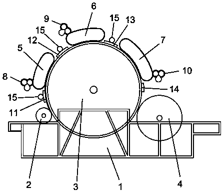
[0024] Carding machine of the present invention, as figure 1 Shown, comprise frame 1, on the frame 1, hair roller 2, cylinder 3 and doffer 4 are installed successively from front to back.

[0025] The top of the cylinder 3 corresponds to the frame 1, and the first carding area cover 5, the second carding area cover 6 and the third carding area cover 7 are installed sequentially from front to back, and the first carding area cover 5 and the second carding area Spaces are provided between the zone covers 6 and between the second carding zone cover 6 and the third carding zone cover 7 .

[0026] The first carding area cover plate 5, the second carding area cover plate 6 and the upper third carding area cover plate 7 are equipped with the first carding area cover plate cleaning device 8, the second carding area cover plate cleaning device 9 and the third carding area respectively. The area cover plate cleaning device 10 enables the three carding area cover plates to be cleaned in...


PUM


Abstract

A carding machine comprises a rack, wherein a licker-in roller, a cylinder and a doffer are successively mounted on the rack from front to back; a first carding region cover plate, a second carding region cover plate and a third carding region cover plate are successively mounted on the top of the cylinder from front to back and correspond to the rack; a gap is formed between the first carding region cover plate and the second carding region cover plate; and a gap is also formed between the second carding region cover plate and the third carding region cover plate. The carding machine is provided with the three carding cover plates, three carding regions are formed, the first carding region has main effects of neatening, smoothly carding fibers and preliminarily discharging impurities andlower piles, the second carding region is further used for neatening, carding the fibers and preliminarily discharging the impurities and the lower piles, the third carding region has main effects ofprecisely carding and further discharging the impurities and lower piles, each of the three carding region cover plates is provided with a cover plate cleaning device, the three carding region cover plates can be cleaned independently, and after being cleaned, the carding cover plates can be rapidly and efficiently used in carding operation. The carding machine is divided into three portions, radian occupied by each carding cover plate is also reduced, the carding cover plates can be cleaned as quickly as possible, the cover plate cleaning efficiency is further improved, and a carding effect is ensured.

Description

technical field [0001] The invention relates to the technical field of textiles, in particular to a carding machine. Background technique [0002] The carding machine is mainly used for carding, removing impurities and collecting various fibers after opening according to the textile process. The carding machine is the most important process in the textile machinery process, which is called the heart of the textile process in the industry. The quality of carding directly affects the quality of the yarn, and the lack of carding and impurity removal in this process cannot be made up by subsequent processes. [0003] The traditional carding machine commonly used at present mainly combs the fibers through a carding surface composed of a set of flat plates and cylinders, and the carding surface composed of flat plates and cylinders quickly preliminarily combs the fibers fed by the licker roller , Most of the fibers that are not firmly held by the cylinder needle teeth are short ...

Claims


Application Information

Patent Timeline
Patent Type & Authority Applications(China)
IPC IPC(8): D01G15/24D01G15/26D01G15/82
CPCD01G15/24D01G15/26D01G15/82
Inventor 曹娜娜
Owner 乐陵市佳和纺织有限公司
Why Eureka
Try Eureka