
Injecting pipe, manufacturing method and gas stove burner therefore

A technology for injection tubes and stoves, which is applied in the field of injection tubes, can solve the problems of affecting the combustion rate, reducing the gas flow rate, and heating of the injection tube, so as to ensure the gas ejection speed, improve high temperature resistance, and improve firmness Effect

Inactive Publication Date: 2019-02-26
李少杰
View PDF0 Cites 0 Cited by
  • Summary
  • Abstract
  • Description
  • Claims
  • Application Information

AI Technical Summary

Problems solved by technology

[0004] The existing burner itself does not have the function of heat insulation. During the normal combustion process of the burner, the fire cover will transfer heat downward during the flame burning process, which will cause the ejector tube to heat up with the increase of use time.
Once the temperature of the injection tube rises, the gas in the injection tube expands to reduce the flow rate of the gas, which affects the uneven mixing of gas and air and affects the combustion rate.
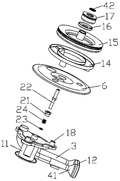
[0005] Moreover, the ignition pins of the existing burners are all fixedly connected to the ejector tube fixing plate. To replace the ignition pins, the burner needs to be disassembled, and it is easy to rust as the use time increases; once rusted, when the ignition pins are damaged, the ignition pins need to be replaced , will bring inconvenience to the replacement of the ignition pin

Method used


Image

  • Injecting pipe, manufacturing method and gas stove burner therefore
  • Injecting pipe, manufacturing method and gas stove burner therefore
  • Injecting pipe, manufacturing method and gas stove burner therefore

Examples


Embodiment 1

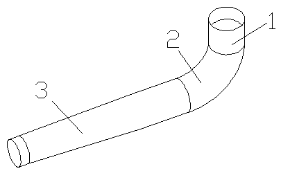
[0038] Such as figure 1 Shown is a kind of injection tube, comprising a first stainless steel hollow injection tube body 1, a stainless steel hollow connection injection tube body 2 and a second stainless steel hollow injection tube body 3, one end of the stainless steel hollow connection injection tube body 2 is connected to The first stainless steel hollow injection tube body 1 is connected, the other end of the stainless steel hollow connection injection tube body 2 is connected with the second stainless steel hollow injection tube body 3, and the first stainless steel hollow injection tube body 1, the stainless steel hollow injection tube body Connecting the ejector body 2 and the second stainless steel hollow ejector body 3 are integrally manufactured without solder joints; the ejector tube of the second stainless steel hollow ejector body 3 that is connected to one end of the stainless steel hollow ejector body 2 The diameter is larger than the diameter of the injection ...

Embodiment 2

[0075] The difference between Example 2 and Example 1 lies in the composition ratio of the raw materials of the high-temperature-resistant heat-insulating coating, which is made of the following raw materials in mass percentage:

[0076] Epoxy modified silicone resin 70%;

[0077] Hollow glass microspheres 12%;

[0078] Low temperature molten glass powder 8%;

[0079] Perlite 7%;

[0080] Dispersant 1%;

[0081] Defoamer 2%.

Embodiment 3

[0083] The difference between Example 3 and Example 1 lies in the composition ratio of the raw materials of the high-temperature-resistant heat-insulating coating, which is made of the following raw materials in mass percentage:

[0084] Epoxy modified silicone resin 66%;

[0085] Hollow glass microspheres 13%;

[0086] Low temperature molten glass powder 9%;

[0087] Perlite 8%;

[0088] Dispersant 2%;

[0089] Defoamer 2%.


PUM


Abstract

The invention discloses an injecting pipe, a manufacturing method and a gas stove burner thereof. The injecting pipe comprises a first stainless steel hollow injecting pipe body, a stainless steel hollow connecting injecting pipe body and a second stainless steel hollow injecting pipe body, one end of the stainless steel hollow connecting injecting pipe body is connected with the first stainless steel hollow injecting pipe body, the other end of the stainless steel hollow connecting injecting pipe body is connected with the second stainless steel hollow injecting pipe body, the first stainlesssteel hollow injecting pipe body, the stainless steel hollow connecting injecting pipe body and the second stainless steel hollow injecting pipe body are integrally manufactured without welding points, and the injecting pipe diameter of the end, close to the stainless steel hollow connecting injecting pipe body, of the second stainless steel hollow injecting pipe body is greater than that of theend, away from the stainless steel hollow connecting injecting pipe body, of the second stainless steel hollow injecting pipe body. The injecting pipe has the advantage that there exists no welding point on the injecting pipe, and therefore the gas leakage of the injecting pipe is prevented.

Description

technical field [0001] The invention relates to an ejector tube, a manufacturing method and a gas stove burner head thereof. Background technique [0002] The injector tube in the existing gas stove burner adopts two sections of injector tube bodies to be welded and fixed or two L-shaped semi-circular arc tube bodies to be fixedly connected by welding, no matter which fixing method is adopted, there are solder joints; Once there are solder joints, as the use time increases, there is bound to be a probability of air leakage, which will cause the burner to be safe to use. [0003] Existing injection tubes are made of aluminum alloy. The injection tube made of aluminum alloy has fast heat conduction, so that the temperature of the injection tube body is easy to rise rapidly. Once the temperature of the injection tube body rises It will cause the gas in the injection tube to expand. Once the gas in the injection tube expands, it will affect the flow rate of the gas in the injec...

Claims


Application Information

Patent Timeline
Patent Type & Authority Applications(China)
IPC IPC(8): F23D14/02F23D14/46
CPCF23D14/02F23D14/46
Inventor 李少杰
Owner 李少杰
Learn More