Cryogenic-liquid forced cooling cable structure

A technology of low temperature liquid and cable structure, which is applied in the field of superconducting transmission, can solve the problems of conductor skin effect, small transmission current, affecting the heat exchange between conductor and low temperature liquid, etc., and achieve the effect of avoiding heat transfer efficiency.

Pending Publication Date: 2019-02-26
SHENZHEN POWER SUPPLY BUREAU
View PDF0 Cites 3 Cited by
  • Summary
  • Abstract
  • Description
  • Claims
  • Application Information

AI Technical Summary

Problems solved by technology

In general, low-temperature cables use liquid nitrogen to directly cool the conductors, but the direct cooling of low-temperature liquids has the following problems: First, the heating of conventional conductors causes the low-temperature liquid to vaporize, and the formed gas film is easy to adhere to the surface of the conductor, thus affecting the connection between the conductor and the low-temperature liquid. Second, the conductor has a skin effect when transmitting a large current, most of the current passes through the conductor near the surface of the conductor, and the middle part of the conductor transmits a small current, which leads to the underutilization of the current-carrying capacity of the conductor

Method used


Image

  • Cryogenic-liquid forced cooling cable structure
  • Cryogenic-liquid forced cooling cable structure
  • Cryogenic-liquid forced cooling cable structure

Examples


Embodiment Construction

[0023] The following will clearly and completely describe the technical solutions in the embodiments of the present invention with reference to the accompanying drawings in the embodiments of the present invention. Obviously, the described embodiments are only part of the embodiments of the present invention, not all of them. Based on the embodiments of the present invention, all other embodiments obtained by persons of ordinary skill in the art without making creative efforts belong to the protection scope of the present invention.

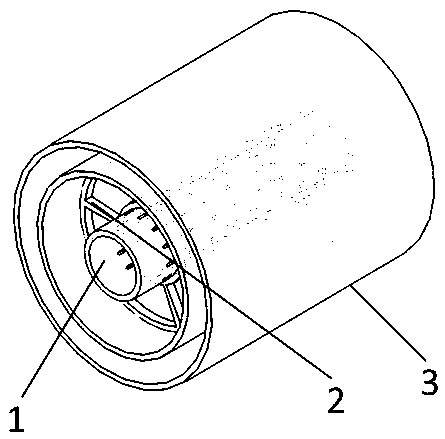
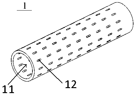
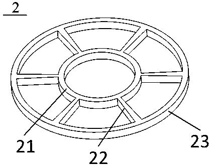
[0024] Such as figure 1 As shown in FIG. 1 , it shows a structural schematic diagram of a cryogenic liquid forced cooling cable structure provided by the present invention. combined Figure 2 to Figure 4 As shown, in this embodiment, the cryogenic liquid forcedly cools the cable structure, which includes a conductor 1, a plurality of support frames 2, and an insulation pipe 3 arranged from the inside to the outside, wherein:

[0025] The conduc...


PUM

PropertyMeasurementUnit
widthaaaaaaaaaa
lengthaaaaaaaaaa
thicknessaaaaaaaaaa

Abstract

The embodiment of the invention discloses a cryogenic-liquid forced cooling cable structure, and the structure comprises a conductor (1), a plurality of supports (2) and a thermal insulation tube (3),wherein the conductor (1), the plurality of supports (2) and the thermal insulation tube (3) are sequentially from the inside to the outside. The conductor (1) is a hollow metal tube, and a side wallof the metal tube is provided with through holes (12) at intervals. The interior of the conductor forms a cryogenic-liquid channel (11), and the supports (2) are each of a hollow-out structure formedby the processing of a non-metal material, and sleeve the conductor (1) at certain intervals. The thermal insulation tube (3) is a high-vacuum thermal insulation tube, and the conductor (1) is disposed in the thermal insulation tube (3) in a coaxially sleeved manner through the supports (2). According to the embodiment of the invention, the structure can improve the thermal conduction efficiencyand avoid the skin effect during the transmission of a large current.

Description

technical field [0001] The invention relates to the field of superconducting transmission, in particular to a low-temperature liquid forced cooling cable structure. Background technique [0002] The resistance of high-purity aluminum or copper will be greatly reduced at low temperature, so it has important applications in occasions such as high current-carrying density and pulse power discharge. In general, low-temperature cables use liquid nitrogen to directly cool the conductors, but the direct cooling of low-temperature liquids has the following problems: First, the heating of conventional conductors causes the low-temperature liquid to vaporize, and the formed gas film is easy to adhere to the surface of the conductor, thus affecting the connection between the conductor and the low-temperature liquid. Second, the conductor has a skin effect when transmitting a large current. Most of the current passes through the conductor near the surface of the conductor, and the middl...

Claims


Application Information

Patent Timeline
Patent Type & Authority Applications(China)
IPC IPC(8): H01B5/06H01B7/30H01B7/40H01B7/42
CPCH01B5/06H01B7/30H01B7/40H01B7/423
Inventor 庞骁刚胡子珩章彬汪桢子汪伟
Owner SHENZHEN POWER SUPPLY BUREAU
Why Eureka
Try Eureka