pucch transmission method, user equipment and device
A transmission method and control channel technology, applied in the field of PUCCH transmission method, user equipment and devices, capable of solving problems such as supporting PUCCH transmission scenarios
- Summary
- Abstract
- Description
- Claims
- Application Information
AI Technical Summary
Problems solved by technology
Method used
Image

Examples
Embodiment 1
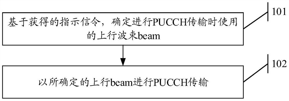
[0550] See figure 1 An embodiment of the present invention provides a PUCCH transmission method, which may be used to perform PUCCH transmission between devices, for example, a user equipment (User Equipment, UE) may perform PUCCH transmission to a base station. Wherein, the user equipment may be a personal computer (PC), a notebook, a mobile phone, an Internet of Things device, a wearable device, etc., and the embodiment of the present invention does not limit the specific type of the user equipment. The base station can be any receiving node, such as TRP, traditional base station, relay node and so on.
[0551] The flow of the PUCCH transmission method in the embodiment of the present invention is described as follows:
[0552] Step 101: Determine an uplink beam used for PUCCH transmission based on the obtained indication signaling.
[0553] Step 102: Perform PUCCH transmission with the determined uplink beam.
[0554] In the embodiment of the present invention, the uplin...
Embodiment 2
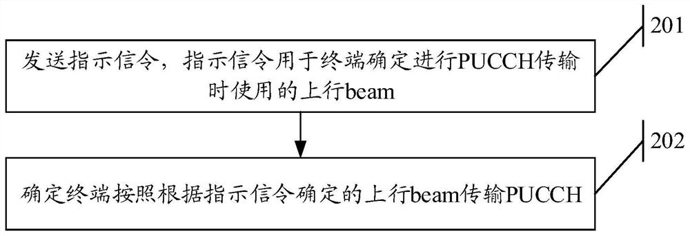
[0653] See figure 2 , based on the same inventive concept as in Embodiment 1, this embodiment of the present invention provides another PUCCH transmission method, which includes the following steps.
[0654] Step 201: Send an indication signaling, the indication signaling is used for the terminal to determine the uplink beam used for PUCCH transmission.
[0655] Step 202: Determine that the terminal transmits the PUCCH according to the uplink beam determined according to the indication signaling.
[0656] In a specific implementation process, the terminal may be a terminal applying the method in Embodiment 1, which is not limited in this embodiment of the present invention.
[0657] In a possible implementation manner, sending the indication signaling, the indication signaling is used for the terminal to determine the uplink beam used for PUCCH transmission, including:
[0658] The indication signaling indicates the beam pair relationship BPL, and the BPL is used to determi...
Embodiment 3
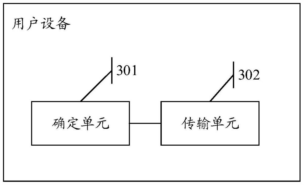
[0747] See image 3 , an embodiment of the present invention provides a user equipment, where the user equipment includes a determining unit 301 and a transmitting unit 302 . in:
[0748] A determining unit 301, configured to determine an uplink beam used for PUCCH transmission based on the obtained indication signaling;
[0749] The transmission unit 302 is configured to perform PUCCH transmission with the determined uplink beam.
[0750] In a possible implementation manner, the determining unit 301 is configured to determine the beam pair relationship BPL based on the obtained instruction, and the BPL is used to determine the relationship between the uplink beam or the demodulation reference signal DMRS port of the PUCCH used for PUCCH transmission and the first Quasi-co-located QCL relationships of ports on resources of reference signals;
[0751] The transmission unit 302 is configured to perform PUCCH transmission with the uplink beam corresponding to the BPL; or, acco...
PUM
 Abstract
Description
Claims
Application Information
 - R&D
- Intellectual Property
- Life Sciences
- Materials
- Tech Scout
- Unparalleled Data Quality
- Higher Quality Content
- 60% Fewer Hallucinations
Browse by: Latest US Patents, China's latest patents, Technical Efficacy Thesaurus, Application Domain, Technology Topic, Popular Technical Reports.
© 2025 PatSnap. All rights reserved.Legal|Privacy policy|Modern Slavery Act Transparency Statement|Sitemap|About US| Contact US: help@patsnap.com