Squeeze bucket for collodion mop

A collodion mop and collodion technology, which is applied in the field of mops, can solve the problems of large weight and volume of mops, inconvenient operation, and laborious drying.

Pending Publication Date: 2019-03-01
夏冬全
View PDF2 Cites 6 Cited by
  • Summary
  • Abstract
  • Description
  • Claims
  • Application Information

AI Technical Summary

Problems solved by technology

But the driving transmission of this collodion mop is carried out by rack and pinion, and needs a plurality of squeezing rollers to roll simultaneously and squeeze dry, therefore, the overall weight and volume of mop are all bigger, and it is also very inconvenient to operate, and squeeze Drying is also more laborious

Method used


Image

  • Squeeze bucket for collodion mop
  • Squeeze bucket for collodion mop
  • Squeeze bucket for collodion mop

Examples


Embodiment Construction

[0021] In order to make the technical means, creative features, goals and effects achieved by the present invention easy to understand, the present invention will be further described below in conjunction with specific embodiments.

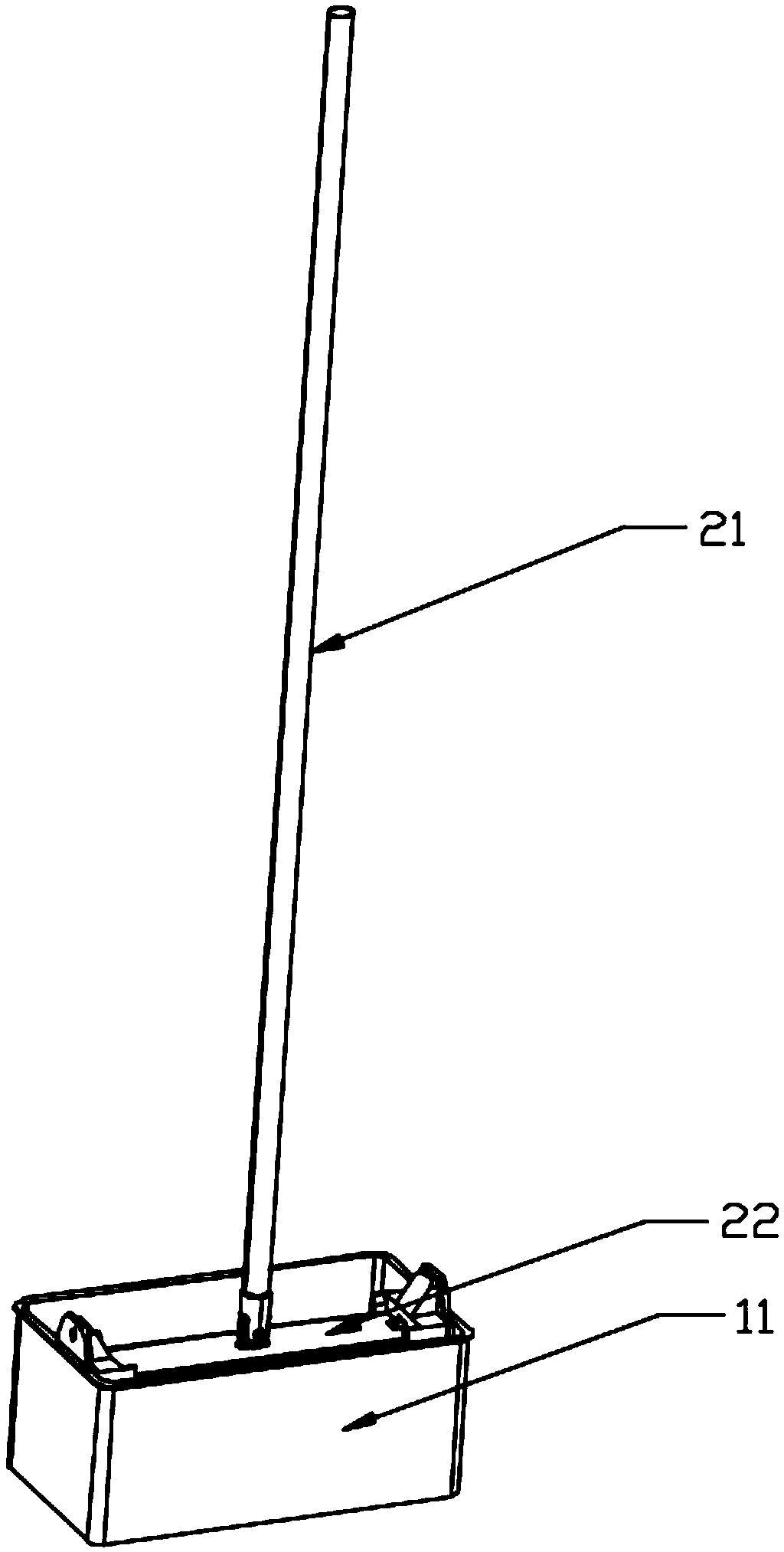
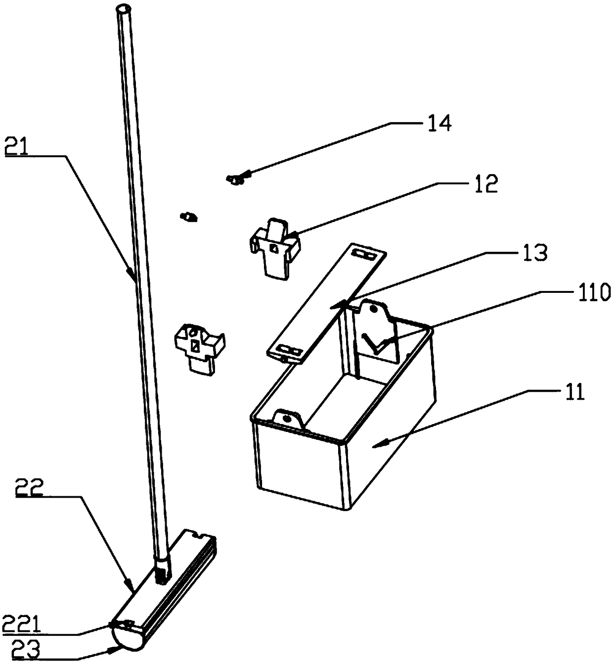
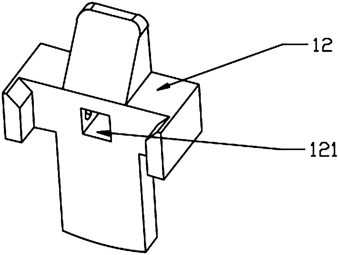
[0022] See Figure 1-6 , the squeeze barrel of the collodion mop according to the first embodiment of the present invention comprises a barrel body 11, and the collodion mop comprises: a mop rod 21, a collodion support part 22 arranged at the lower end of the mop rod 21, a collodion support part 22 arranged at the lower end of the collodion The collodion head 23 on the lower surface of the support part 22, the squeeze barrel also includes a pair of swing frames 12 whose upper part is hinged on the upper part of the barrel body 11, an extruding plate 13 slidingly connected to the bottom of the swing frame 12, and a pair of swing frames arranged on the swing frame. 12. The reaction force supporting part 14 on the upper part, the barrel body 11 is al...


PUM


Abstract

The invention relates to the field of mops, in particular to a squeeze bucket for a collodion mop. The squeeze bucket further comprises a pair of swing frames with the upper portions being hinged to the upper portions of a bucket body, a squeeze plate slidingly connected with the lower portions of the swing frames and counter-force supporting parts arranged at the upper portions of the swing frames; the bucket body is further provided with a guide part which cooperates with the squeeze plate and is used for guiding the squeeze plate to extrude a collodion head during the rotation of the swingframes. A user can drive the swing frames to rotate through a mop rod, and the squeeze plate is guided by the guide part to squeeze the collodion head along with the rotation of the swing frames to complete the squeeze. The length of the mop rod is long, so that only very little force is required for the user to drive the swing frames to rotate.

Description

technical field [0001] The invention relates to the field of mops, in particular to a squeeze barrel of a collodion mop. Background technique [0002] The collodion mop is one of the mops with foamed cotton heads. The existing collodion mop, such as a collodion mop disclosed in Chinese Patent Announcement No. CN202681861U, includes a mop, a handle, and a mop connected to the end of the mop. The connected V-shaped bracket, the left rotating part and the right rotating part connected to the two ends of the V-shaped bracket respectively, the left folding plate assembly and the right folding plate assembly respectively connected with the left rotating part and the right rotating part , the connecting piece connected between the left folding plate assembly and the right folding plate assembly, and the collodion drag head connected to the left folding plate assembly and the right folding plate assembly, the left folding plate assembly and the right folding plate assembly are respe...

Claims


Application Information

Patent Timeline
IPC IPC(8): A47L13/59A47L13/257
CPCA47L13/257A47L13/59
Inventor 夏冬全
Owner 夏冬全
Why Eureka
Try Eureka