A remote diagnosis and treatment system for knee osteoarthritis based on infrared imaging

A knee osteoarthritis, remote diagnosis and treatment technology, applied in the direction of diagnosis, spectrum diagnosis, diagnosis recording/measurement, etc., to avoid the possibility of subjective judgment error, save time and money

Active Publication Date: 2022-03-15
SHUGUANG HOSPITAL AFFILIATED WITH SHANGHAI UNIV OF T C M
View PDF11 Cites 0 Cited by
  • Summary
  • Abstract
  • Description
  • Claims
  • Application Information

AI Technical Summary

Problems solved by technology

No related reports

Method used


Image

  • A remote diagnosis and treatment system for knee osteoarthritis based on infrared imaging
  • A remote diagnosis and treatment system for knee osteoarthritis based on infrared imaging
  • A remote diagnosis and treatment system for knee osteoarthritis based on infrared imaging

Examples


Embodiment 1

[0053] Embodiment 1 The remote diagnosis and treatment system for knee osteoarthritis based on infrared imaging of the present invention (1)

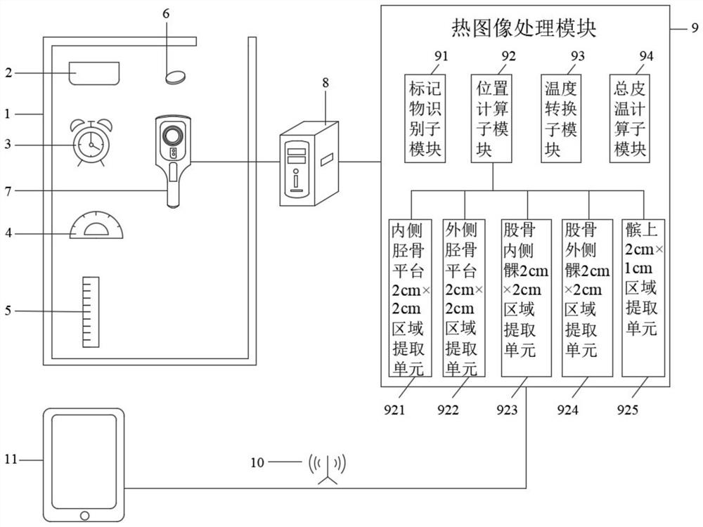
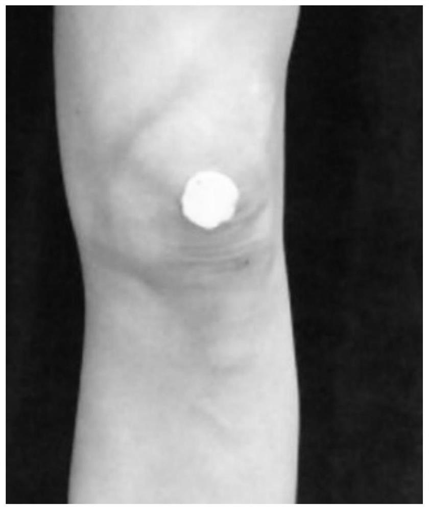
[0054] See figure 1 , figure 1 It is a structural block diagram of a remote diagnosis and treatment system for knee osteoarthritis based on infrared imaging in the present invention. The remote diagnosis and treatment system for knee osteoarthritis based on infrared imaging includes a detection room 1. The detection room 1 is equipped with a temperature control device 2, and the detection room 1 is also equipped with a timer 3, an angle calibration component 4, and a distance calibration unit. Component 5, marker 6, infrared camera 7. The detection room 1 may be a bedroom at home. The temperature control device 2 may be an air conditioner, and is used to control the temperature of the detection chamber 1, and generally controls the temperature of the detection chamber 1 at 23±3°C. The timer 3 is used to count the time to ensure that...

Embodiment 2

[0063] Embodiment 2 The remote diagnosis and treatment system for knee osteoarthritis based on infrared imaging of the present invention (2)

[0064] See Figure 4 , Figure 4It is a structural block diagram of another remote diagnosis and treatment system for knee osteoarthritis based on infrared imaging in the present invention. The remote diagnosis and treatment system for knee osteoarthritis based on infrared imaging includes a detection room 1. The detection room 1 is equipped with a temperature control device 2, and the detection room 1 is also equipped with a timer 3, an angle calibration component 4, and a distance calibration unit. Component 5, marker 6, infrared camera 7. The detection room 1 may be a bedroom at home. The temperature control device 2 may be an air conditioner, and is used to control the temperature of the detection chamber 1, and generally controls the temperature of the detection chamber 1 at 23±3°C. The timer 3 is used to count the time to ensu...

Embodiment 3

[0068] Embodiment 3 Infrared imaging-based research method of knee osteoarthritis for non-diagnostic and therapeutic purposes of the present invention

[0069] A method for researching knee osteoarthritis based on infrared imaging for non-diagnostic and therapeutic purposes of the present invention, which is based on the remote diagnosis and treatment system for knee osteoarthritis based on infrared imaging described in Embodiment 1 or 2, specifically includes the following steps:

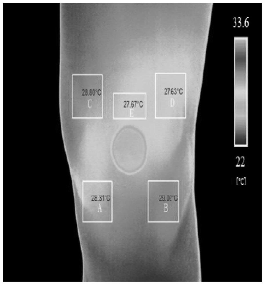
[0070] Step S1: Use the temperature control device to adjust the temperature of the testing room to about 23°C and keep the temperature without too much fluctuation. Let the subject expose the affected knee joint for 10 minutes in the testing room with a constant temperature (use a timer to determine the time) , using the angle calibration component to adopt a 15° foot external rotation standing position, and then collect skin temperature information on the knee joint of the subject. Keep a constan...


PUM


Abstract

The invention relates to a remote diagnosis and treatment system for knee osteoarthritis based on infrared imaging, which includes a detection room equipped with a temperature control device, a timer, an angle calibration component, a distance calibration component, markers, an infrared thermal imager, a computer, and a thermal image Processing module, network and diagnosis and treatment terminal; the thermal image processing module is used to extract the position of the marker and use this as a reference to calculate and extract the temperature of the following five areas: medial tibial plateau 2cm×2cm area, lateral tibial plateau 2cm×2cm region, medial femoral condyle 2cm×2cm region, lateral femoral condyle 2cm×2cm region, and suprapatellar 2cm×1cm region; the network transmits the results extracted by the thermal image processing module to the diagnosis and treatment terminal so that doctors can make further diagnoses. The invention can remotely provide doctors and experts with accurate knee joint skin temperature values ​​for patients with knee osteoarthritis, so as to help doctors and experts make early diagnosis and formulate treatment plans, and benefit patients.

Description

technical field [0001] The invention relates to the technical field of medical equipment, in particular to a remote diagnosis and treatment system for knee osteoarthritis based on infrared imaging. Background technique [0002] Infrared thermal imaging is a functional diagnostic technology that passively receives the infrared radiation of the human body. It does not touch the human body, emits no radiation, and has no damage or side effects to the human body. It can detect, record and image the temperature of the human body surface and thermal regions. It can capture the surface temperature distribution and then provide physiological state information such as tissue thermal, metabolic and blood vessels that are closely related to the physiological state of the human body. It has been applied in many clinical fields. Infrared thermal images can provide temperature contrast information of the detected area. Qualitative and quantitative detection is performed on the detected ar...

Claims


Application Information

Patent Timeline
Patent Type & Authority Patents(China)
IPC IPC(8): A61B5/00A61B5/01
CPCA61B5/0015A61B5/0064A61B5/0075A61B5/01
Inventor 曹月龙薛艳蒋鼎顾思臻庞坚郑昱新
Owner SHUGUANG HOSPITAL AFFILIATED WITH SHANGHAI UNIV OF T C M
Why Eureka
Try Eureka