Mechanical gear repairing punching auxiliary mechanism

An auxiliary mechanism and gear technology, applied in the direction of boring/drilling, drilling/drilling equipment, parts of boring machine/drilling machine, etc. The effect of unstable deviation, improving work efficiency and reducing damage rate

Active Publication Date: 2019-03-01
ZHEJIANG ZHENHUA FORGING GEAR CO LTD
View PDF8 Cites 1 Cited by
  • Summary
  • Abstract
  • Description
  • Claims
  • Application Information

AI Technical Summary

Problems solved by technology

[0002] The equipment in the factory workshop will contain some gears for mechanical transmission. After a long time, it will cause the wear of the gears, and even the teeth on some gears will break. In order to make the equipment work normally, people usually use the The broken tooth is re-welded on the gear to keep the gear intact, but the directly welded broken tooth is not tightly connected to the gear, and it will break after a period of use. The service life is short, and welding must be performed after breaking, and repeated welding It will inevitably increase the maintenance cost and affect the progress of the work, and even cause the broken teeth of the gears to be damaged and unusable. In order to avoid repeated welding, people will drill holes on the gears, fill the holes with iron nails and other objects, and put the gears and broken teeth together. Connected together, so that the broken teeth after welding are more closely connected with the gear, and the use time is longer. However, people tend to miss the hole when drilling, and the bit will break if they are not careful. Improper operation is also easy to be injured, and the safety is low. , the position is not accurate when punching, and it needs to be punched multiple times

Method used


Image

  • Mechanical gear repairing punching auxiliary mechanism
  • Mechanical gear repairing punching auxiliary mechanism
  • Mechanical gear repairing punching auxiliary mechanism

Examples


Embodiment 1

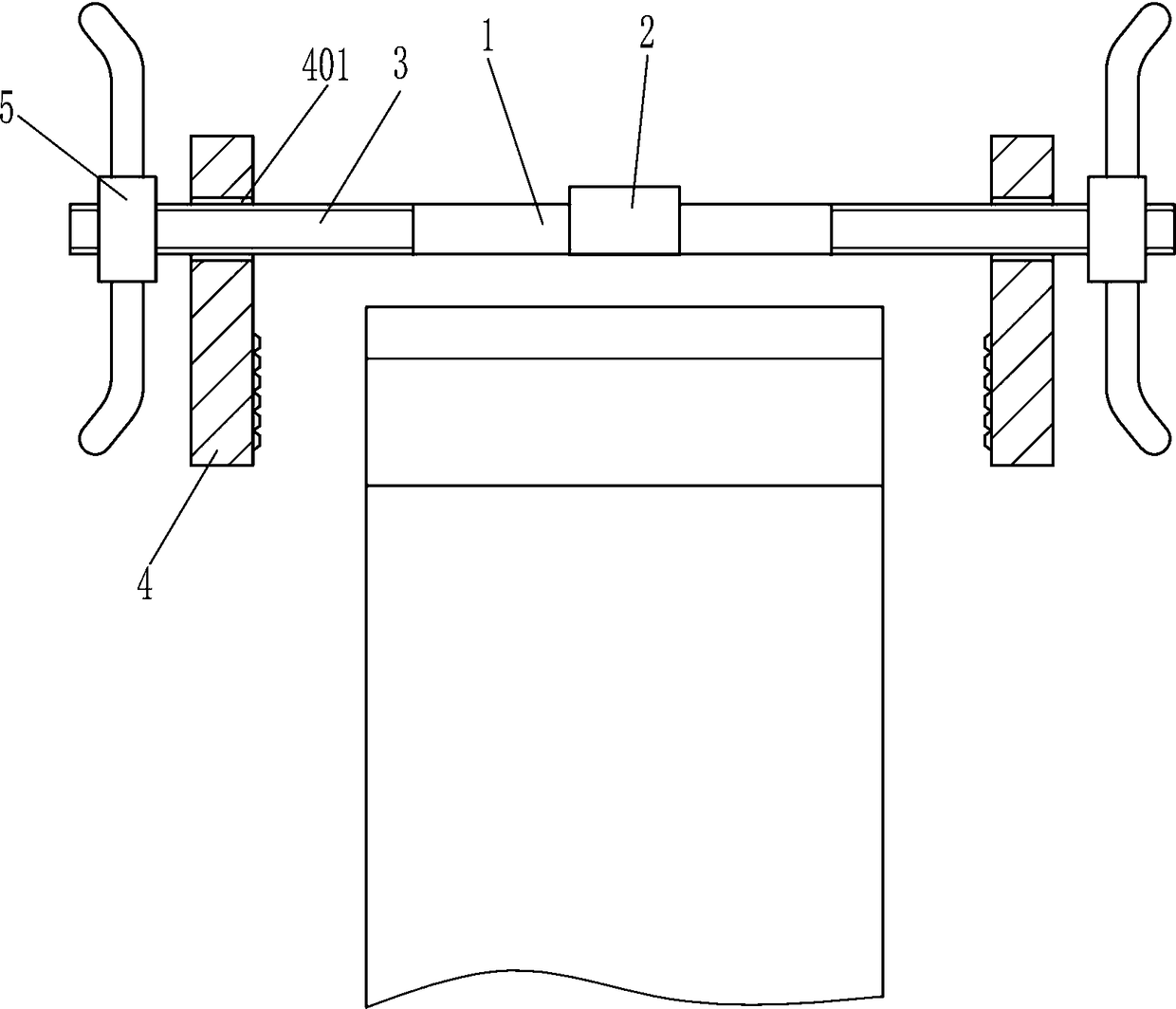
[0020] A mechanical gear repair punching auxiliary mechanism, such as Figure 1-4 As shown, it includes a guide rail 1, a screw 3, a splint 4 and a wing nut 5, the left and right sides of the guide rail 1 are provided with a screw 3, the screw 3 is provided with a splint 4 and a wing nut 5, and the left splint 4 is located on the left On the right side of the butterfly nut 5, the right splint 4 is located on the left side of the right wing nut 5, the upper part of the splint 4 has a slide hole 401, the outer end of the screw rod 3 passes through the slide hole 401, and the middle part of the guide rail 1 has a through hole 102.

Embodiment 2

[0022] A mechanical gear repair punching auxiliary mechanism, such as Figure 1-4 As shown, it includes a guide rail 1, a screw 3, a splint 4 and a wing nut 5, the left and right sides of the guide rail 1 are provided with a screw 3, the screw 3 is provided with a splint 4 and a wing nut 5, and the left splint 4 is located on the left On the right side of the butterfly nut 5, the right splint 4 is located on the left side of the right wing nut 5, the upper part of the splint 4 has a slide hole 401, the outer end of the screw rod 3 passes through the slide hole 401, and the middle part of the guide rail 1 has a through hole 102.

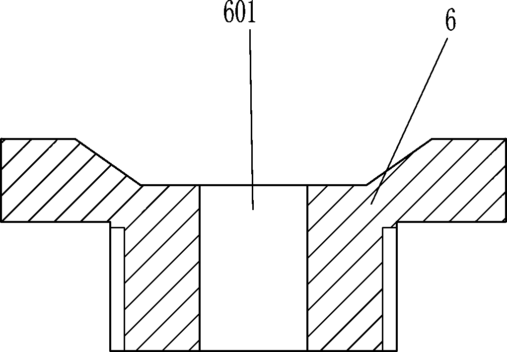
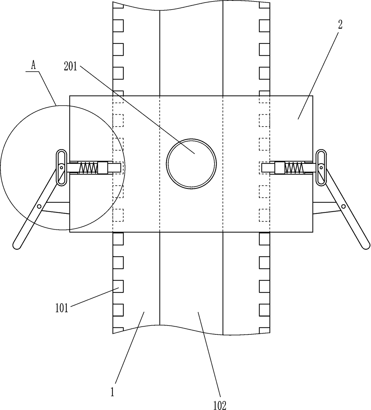
[0023] It also includes a guide block 2, which slides on the guide rail 1 and is provided with a threaded hole 201 in the middle of the guide block 2. The threaded hole 201 is located directly above the through hole 102, and there are grooves 101 on the front and rear sides of the guide rail 1. .

Embodiment 3

[0025] A mechanical gear repair punching auxiliary mechanism, such as Figure 1-4 As shown, it includes a guide rail 1, a screw 3, a splint 4 and a wing nut 5, the left and right sides of the guide rail 1 are provided with a screw 3, the screw 3 is provided with a splint 4 and a wing nut 5, and the left splint 4 is located on the left On the right side of the butterfly nut 5, the right splint 4 is located on the left side of the right wing nut 5, the upper part of the splint 4 has a slide hole 401, the outer end of the screw rod 3 passes through the slide hole 401, and the middle part of the guide rail 1 has a through hole 102.

[0026] It also includes a guide block 2, which slides on the guide rail 1 and is provided with a threaded hole 201 in the middle of the guide block 2. The threaded hole 201 is located directly above the through hole 102, and there are grooves 101 on the front and rear sides of the guide rail 1. .

[0027] Also include nail 203, slide block 204, spri...


PUM


Abstract

The invention relates to a punching mechanism, in particular to a mechanical gear repairing punching auxiliary mechanism. The technical problem is that the mechanical gear repairing punching auxiliarymechanism which can fix the punching position and reduce the damage rate of a drill bit, and has high safety is provided. The technical scheme is that the mechanical gear repairing punching auxiliarymechanism comprises a guiding rail and the like; and threaded rods are arranged on the left and right sides of the guiding rail, the threaded rods are provided with clamping plates and wing nuts, andleft clamping plate is located at the right parts of left wing nuts, right clamping plates are located at the right parts of left wing nuts, right clamping plates are located at the left parts of right wing nuts, sliding holes are formed in the upper parts of the clamping plates, the outer ends of threaded rods penetrate through the sliding holes, and a straight-through hole is formed in the middle part of the guiding rail. According to the mechanical gear repairing punching auxiliary mechanism, the position of punching is fixed through the straight-through hole in the guiding rail and a threaded hole in a guiding block, a sprigging is inserted into a corresponding groove realizing fixing of the position of the guiding block, and then the punching is carried out in a gear, after the position of the punching is found accurately, the working efficiency can be improved, the damage rate of the drill bit is reduced, and the cost is saved.

Description

technical field [0001] The invention relates to a punching mechanism, in particular to a mechanical gear repairing and punching auxiliary mechanism. Background technique [0002] The equipment in the factory workshop will contain some gears for mechanical transmission. After a long time, the gears will wear out, and even the teeth on some gears will break. In order to make the equipment work normally, people usually use the The broken teeth are re-welded on the gears to keep the gears intact, but the directly welded broken teeth are not tightly connected to the gears, and will break after a period of use. The service life is short, and welding must be performed after breaking, and repeated welding It will inevitably increase the maintenance cost and affect the progress of the work, and even cause the broken teeth of the gears to be damaged and unusable. In order to avoid repeated welding, people will drill holes on the gears, fill the holes with iron nails and other objects,...

Claims


Application Information

Patent Timeline
Patent Type & Authority Applications(China)
IPC IPC(8): B23B41/00B23B47/00
CPCB23B41/00B23B47/00
Inventor 郭才剑
Owner ZHEJIANG ZHENHUA FORGING GEAR CO LTD
Why Eureka
Try Eureka