Laser welding method
A laser welding and laser technology, applied in laser welding equipment, welding equipment, metal processing equipment, etc., can solve the problems of small joint area and low strength
- Summary
- Abstract
- Description
- Claims
- Application Information
AI Technical Summary
Problems solved by technology
Method used
Image
Examples
Embodiment 1
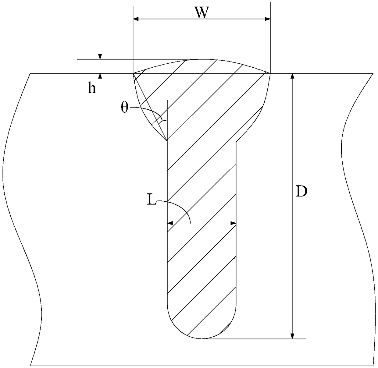
[0064] In this example, laser welding is carried out for SUS316 stainless steel with a thickness of 4.0mm. Before welding, the surface of the material is cleaned with alcohol, and then the workpiece is fixed with a clamp. The workpiece is welded in a way that the beam does not swing. The laser power used is 300W, the welding speed is 20mm / s, and the welding is performed at the focal point. The coaxial direct blowing shielding gas is used. The shielding gas is pure argon, and the gas flow rate is 15L / min. After welding, make metallographic observation and measure the cross section of weld seam. The test results are as follows: Figure 5 As shown, the weld cross section is Y-shaped, the weld penetration depth is 1.65mm, the fusion width is 0.64mm, and the weld waist length is small.
Embodiment 2
[0066] In this example, laser welding is carried out for SUS316 stainless steel with a thickness of 4.0mm. Before welding, the surface of the material is cleaned with alcohol, and then the workpiece is fixed with a clamp. The workpiece is welded in the way of linear swing, the swing amplitude is 0.2mm, the swing frequency is 1000Hz, the laser power used is 900W, the welding speed is 20mm / s, the welding is at the focus position, and the coaxial direct blowing shielding gas is used, and the shielding gas is pure argon. The air flow is 15L / min. After welding, make metallographic observation and measure the cross section of weld seam. The test results are as follows: Figure 6 As shown, the cross-section of the weld is rectangular, and the weld width is approximately equal to the waist length. The weld penetration depth is 1.57mm, the weld width is 1.39mm, and there are no pores, cracks and other defects inside the weld.
Embodiment 3
[0068] In this example, laser welding is carried out for SUS316 stainless steel with a thickness of 4.0mm. Before welding, the surface of the material is cleaned with alcohol, and then the workpiece is fixed with a clamp. The workpiece is welded in the way of linear swing, the swing amplitude is 0.1mm, the swing frequency is 1000Hz, the laser power used is 900W, the welding speed is 20mm / s, the welding is at the focal point, and the coaxial direct blowing shielding gas is used, and the shielding gas is pure argon. The air flow is 15L / min. After welding, make metallographic observation and measure the cross section of weld seam. The test results are as follows: Figure 7 As shown, the cross-section of the weld is inverted trapezoid, the weld penetration depth is 2.4mm, the fusion width is 1.29mm, and there are no pores, cracks and other defects inside the weld.
PUM
| Property | Measurement | Unit |
|---|---|---|
| Diameter | aaaaa | aaaaa |
| Semi-major axis | aaaaa | aaaaa |
| Semi-major axis | aaaaa | aaaaa |
Abstract
Description
Claims
Application Information
 - R&D
- Intellectual Property
- Life Sciences
- Materials
- Tech Scout
- Unparalleled Data Quality
- Higher Quality Content
- 60% Fewer Hallucinations
Browse by: Latest US Patents, China's latest patents, Technical Efficacy Thesaurus, Application Domain, Technology Topic, Popular Technical Reports.
© 2025 PatSnap. All rights reserved.Legal|Privacy policy|Modern Slavery Act Transparency Statement|Sitemap|About US| Contact US: help@patsnap.com


