Formation machine for surface pattern of automobile sealing strip

A technology for automotive sealing strips and forming machines, which is applied in the field of auto parts processing, can solve the problems of single pattern forming function, inability to process intermittent patterns, and lack of sealing strips, etc., so as to avoid inconvenience of movement, good forming effect and high forming efficiency Effect

Active Publication Date: 2019-03-01
浙江祥晋汽车零部件股份有限公司
View PDF5 Cites 1 Cited by
  • Summary
  • Abstract
  • Description
  • Claims
  • Application Information

AI Technical Summary

Problems solved by technology

[0005] Sealing strip is one of the important parts of automobiles. It is widely used in many parts such as doors, windows, and bodywork. It plays an important role in sound insulation, dustproof, and waterproof. With the popularization of vehicle applications, and users With the improvement of the aesthetic requirements of vehicles, it is often necessary to carry out necessary beautification treatment on the sealing strip of the vehicle. Among them, making a specific pattern on the surface of the sealing strip is one of the common methods for beautifying the sealing strip; in order to realize the surface processing of the sealing strip The need for patterns is currently mainly in the production process of sealing strips. When the sealing strips are extruded and formed, the surface of the sealing strips is processed by pattern rolling with patterned roller equipment. Although this method can meet the needs of pattern processing, it is also necessary. It is found that this pattern processing method is extremely inflexible, especially it does not have the ability to process the pattern on the formed sealing strip, and the pattern processed by the pattern roller during the extrusion of the sealing strip can only be a continuous pattern, not Process intermittent pattern, single pattern forming function

Method used


Image

  • Formation machine for surface pattern of automobile sealing strip
  • Formation machine for surface pattern of automobile sealing strip
  • Formation machine for surface pattern of automobile sealing strip

Examples


Embodiment 1

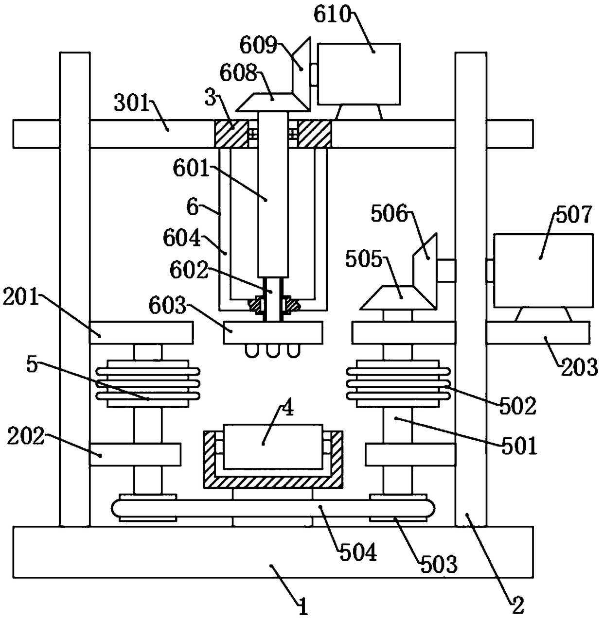
[0034] Please refer to the accompanying drawings, the present invention provides a technical solution: a surface pattern forming machine for automobile weather strips, including a base 1, a lateral embossing mechanism 5 and a vertical embossing mechanism 6, characterized in that the base 1 Vertical side plates 2 are symmetrically fixed on both sides of the top surface, and a top plate 207 is arranged between the tops of the side plates 2. The lateral embossing mechanism 5 includes two sets of embossing components, which are respectively arranged inside the two side plates 2. The bottom of the side and the support assembly 4 are arranged between the two groups of embossing assemblies. The vertical embossing mechanism 6 is arranged on the top plate 207 and above the support assembly 4 .

[0035] The top surface of the base plate is provided with an adjustment groove 101, and two adjustment screw rods 105 are rotationally connected in the adjustment groove 101, and the direction o...

Embodiment 2

[0042] A surface pattern molding machine for automobile weather strips, comprising a base 1, a lateral embossing mechanism 5 and a vertical embossing mechanism 6, characterized in that vertical side plates 2 are symmetrically fixed on both sides of the top surface of the base 1, A top plate 207 is provided between the tops of the side plates 2, and the lateral embossing mechanism 5 includes two groups of embossing assemblies, which are respectively arranged at the bottom of the inner sides of the two side plates 2, and between the two groups of embossing assemblies is provided The support assembly 4 , the vertical embossing mechanism 6 is arranged on the top plate 207 and above the support assembly 4 .

[0043] The top surface of the base plate is provided with an adjustment groove 101, and two adjustment screw rods 105 are rotationally connected in the adjustment groove 101, and the direction of rotation of the two adjustment screw rods 105 is opposite, and the inner ends of t...

Embodiment 3

[0052] The structure of this embodiment is basically the same as that of Embodiment 2. The difference is that the drive mechanism 8 includes a drive box 801, a first rack 806 and a second rack 807, and a camshaft 802 is rotatably connected to the drive box 801. One end of the camshaft 802 is connected to the drive motor 803, the camshaft 802 is provided with a first cam 804 and a second cam 805, and one end of the first rack 806 and the second rack 807 passes through the drive box 801 respectively The top surface and the bottom surface of the rack are respectively meshed with the third gear 705 and the second gear 508, and the inner ends of the first rack 806 and the second rack 807 are respectively in contact with the wheel surfaces of the first cam 804 and the second cam 805, Moreover, the first rack 806 and the second rack 807 are provided with spring plates 808 , and the two spring plates 808 are respectively connected to the top surface and the bottom surface of the drivin...


PUM


Abstract

The invention discloses a formation machine for a surface pattern of an automobile sealing strip and relates to the technical field of automobile part processing. The machine comprises a base, a lateral knurling mechanism, a vertical knurling mechanism, a transmission mechanism and a driving mechanism. According to the formation machine, the sealing strip is more conveniently and flexibly moved through a rolling shaft of a supporting assembly, during lateral knurling, a first motor drives knurling wheels at the two sides through a transmission belt to rotate simultaneously, and the side edge of the sealing strip is subjected to continuous pattern yoking formation; during vertical knurling, the first motor stops rotation, a second motor is started, a thread cylinder rotates through transmission of a third bevel gear and a fourth bevel gear, a thread rod moves downwards through structures such as a limit rack, a sleeve and limit blocks, a knurling plate moves downwards, the top of the sealing strip is subjected to discontinuous pattern formation, the processes are repeatedly conducted, the formed sealing strip is subjected to pattern formation work, and two kinds of patterns are formed on the same sealing strip.

Description

technical field [0001] The invention relates to the technical field of automobile parts processing, in particular to an automobile sealing strip surface pattern forming machine. Background technique [0002] Sealing strip is a product that seals something so that it is not easy to open, and has the functions of shock absorption, waterproof, sound insulation, heat insulation, dustproof, fixing, etc. Sealing strips are made of rubber, paper, metal, plastic and other materials. [0003] According to the cross-sectional shape, the sealing strip can be divided into solid core products (round, square, flat cross-sectional shapes), hollow products and metal-rubber composite products. Among them, metal-rubber composite sealing strips account for more than 60%. Sectional design is very important for rubber sealing strips. The first is the shape and size design of the sealing lip. The sealing lips on both sides should contact the glass from both sides of the window glass with the s...

Claims


Application Information

Patent Timeline
Patent Type & Authority Applications(China)
IPC IPC(8): B29C59/02B29C59/04
CPCB29C59/02B29C59/04
Inventor 颜涛
Owner 浙江祥晋汽车零部件股份有限公司
Why Eureka
Try Eureka