
Arresting hook mechanism for unmanned aerial vehicle

An arresting hook and UAV technology, which is applied to arrester hooks and other directions, can solve the problems of arresting hook bounce, arresting failure, and complex structure, and achieve the effects of convenient maintenance, simple structure and small size.

Pending Publication Date: 2019-03-01
西安爱生无人机技术有限公司
View PDF0 Cites 3 Cited by
  • Summary
  • Abstract
  • Description
  • Claims
  • Application Information

AI Technical Summary

Problems solved by technology

[0007] The purpose of the present invention is to provide an arresting hook mechanism for unmanned aerial vehicles to solve the existing arresting hook mechanism that makes the arresting hook reach the working position through the dead weight of the arresting hook. The arresting hook mechanism that controls the arresting hook in place by the operating mechanism has a technical problem that its structure is too complicated

Method used


Image

  • Arresting hook mechanism for unmanned aerial vehicle
  • Arresting hook mechanism for unmanned aerial vehicle
  • Arresting hook mechanism for unmanned aerial vehicle

Examples


Embodiment Construction

[0048] The present invention will be described in detail below in conjunction with the accompanying drawings and specific embodiments.

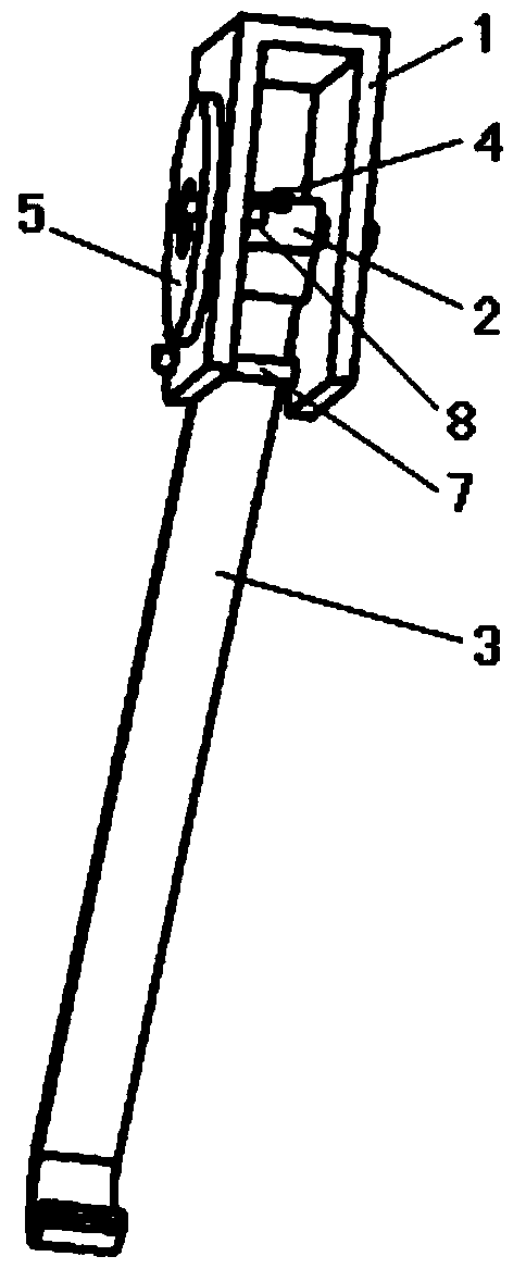
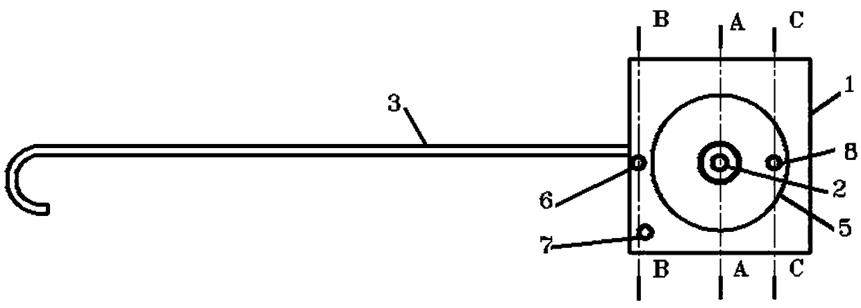
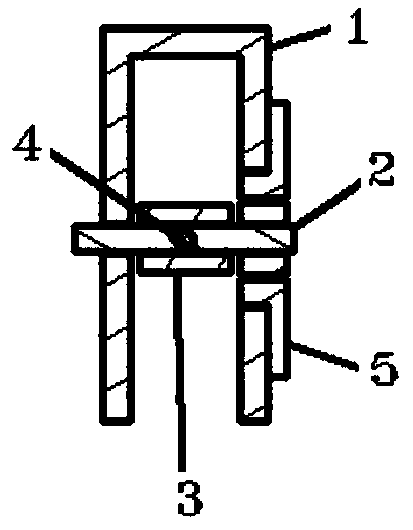
[0049] see figure 1 , figure 2 , Image 6 and Figure 9 , an arresting hook mechanism for an unmanned aerial vehicle in the present invention includes a bracket 1 , a one-way mechanism 5 , an arresting hook shaft 2 , an arresting hook 3 , an opening and closing mechanism 6 , a limiting structure 7 and a reset mechanism 8 .

[0050] Bracket 1, as the main supporting structure of the mechanism, plays the role of supporting other structures and connecting with the drone body. Bracket 1 includes a fixed first mounting plate and a second mounting plate, the first mounting plate and the second mounting plate They are parallel to each other with a gap in the middle. In this embodiment, the bracket 1 is U-shaped, and the above-mentioned first mounting plate and second mounting plate correspond to two sides of the U-shape. The one-way mechanism 5...


PUM


Abstract

The invention relates to a taxiing-landing arresting mechanism for an unmanned aerial vehicle, in particular to an arresting hook mechanism for the unmanned aerial vehicle and solves problems of arresting failure caused by bouncing of an arresting hook reaching an operating position under the dead weight of the arresting hook of an existing arresting hook mechanism and structural complexity of thearresting hook controlled in place through a control mechanism. The arresting hook mechanism is characterized in that a supporting frame comprises a first mounting plate and a second mounting plate,and the first mounting plate and the second mounting plate are parallel and spaced; a unidirectional mechanism comprises an inner ring and an outer ring, and the inner ring and the outer ring are coaxial and capable of relatively unidirectionally rotating; one end of an arresting hook shaft is in rotational connection with the first mounting plate while the other end is fixedly connected with theinner ring of the unidirectional mechanism; the outer ring of the unidirectional mechanism is in rotational connection with the second mounting plate; one end of the arresting hook is fixedly connected with a portion, between the first mounting plate and the second mounting plate, of the arresting hook shaft while the other end is provided with a bent hook; a limiting structure is arranged betweenthe first mounting plate and the second mounting plate and positioned below an opening-closing mechanism; by a resetting mechanism, positioning connection between the outer ring of the unidirectionalmechanism and the second mounting plate is realized.

Description

technical field [0001] The invention relates to an arresting mechanism for a UAV sliding and landing, in particular to an arresting hook mechanism for an UAV. Background technique [0002] At present, UAVs have been widely used in many fields such as reconnaissance, surveillance, target positioning, target damage assessment, electronic countermeasures, and communication relay. Due to the advantages of UAVs such as low cost, good penetration capabilities and their outstanding performance in practice, users urgently need a variety of UAVs that are easy to use and have excellent performance. Therefore, safety, reliability, economy and usability requirements It is the biggest challenge to UAV design. [0003] There are many ways to recover UAVs now, among which parachute recovery and sliding landing recovery are widely used. Parachute recovery means that the UAV opens the parachute in the air and brings the UAV to a smooth landing at a small speed. Rolling and landing recover...

Claims


Application Information

Patent Timeline
IPC IPC(8): B64C25/68
CPCB64C25/68Y02T50/40
Inventor 汪强李德庚冯阳建王国飞周明
Owner 西安爱生无人机技术有限公司
Learn More