Transport device for medical wastes of surgery department

A technology of medical waste and transportation devices, which is applied in the direction of transportation and packaging, conveyors, conveyor objects, etc., and can solve the problems of no way to change the rate of transporting waste and reducing the rate of waste treatment

Inactive Publication Date: 2019-03-01
吴凯
View PDF6 Cites 2 Cited by
  • Summary
  • Abstract
  • Description
  • Claims
  • Application Information

AI Technical Summary

Problems solved by technology

[0002] For example, the patent number is CN201610188557.1, a new type of garbage transportation device, including a car body, an upper cover plate, a connecting rod, a hydraulic rod, and an engine energy recovery device. The above cover is connected, one end of the hydraulic rod is connected with one of the connecting rods, and the other end is hinged on the car body; the garbage transport device is driven by the engine, and the engine energy recovery device is used to recover the heat of the engine exhaust, but the invention The disadvantage is that there is no way to change the rate at which garbage can be transported, which in turn reduces the rate of garbage disposal

Method used


Image

  • Transport device for medical wastes of surgery department
  • Transport device for medical wastes of surgery department
  • Transport device for medical wastes of surgery department

Examples


specific Embodiment approach 1

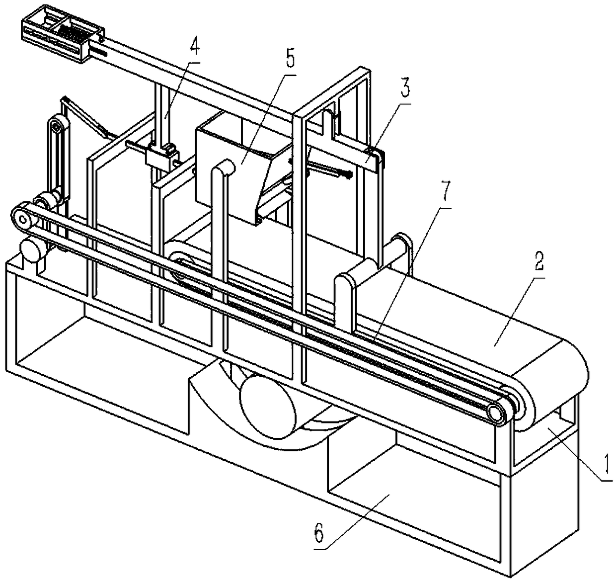
[0041] Combine below Figure 1-23 Describe this embodiment, a transportation device for traumatology medical waste, including a support frame assembly 1, a conveyor belt assembly 2, a counterweight clamp assembly 3, a tapered slide rod 4, a feeding end 5, a vibration balance The terminal 6 and the rotating belt 7 are characterized in that: the right end of the conveyor belt assembly 2 is hingedly connected to the right end of the support frame assembly 1, and the middle end of the counterweight clamping assembly 3 is hingedly connected to the support frame assembly 1 On the upper side of the middle end, the lower end of the tapered slide rod 4 is connected to the support frame assembly 1 through clearance fit, and the upper end of the tapered slide rod 4 is fixedly connected to the middle end of the lower end surface of the counterweight clamping assembly 3, and the feeding end The front and rear ends of 5 are respectively fixedly connected to the support frame assembly 1, the...

specific Embodiment approach 2

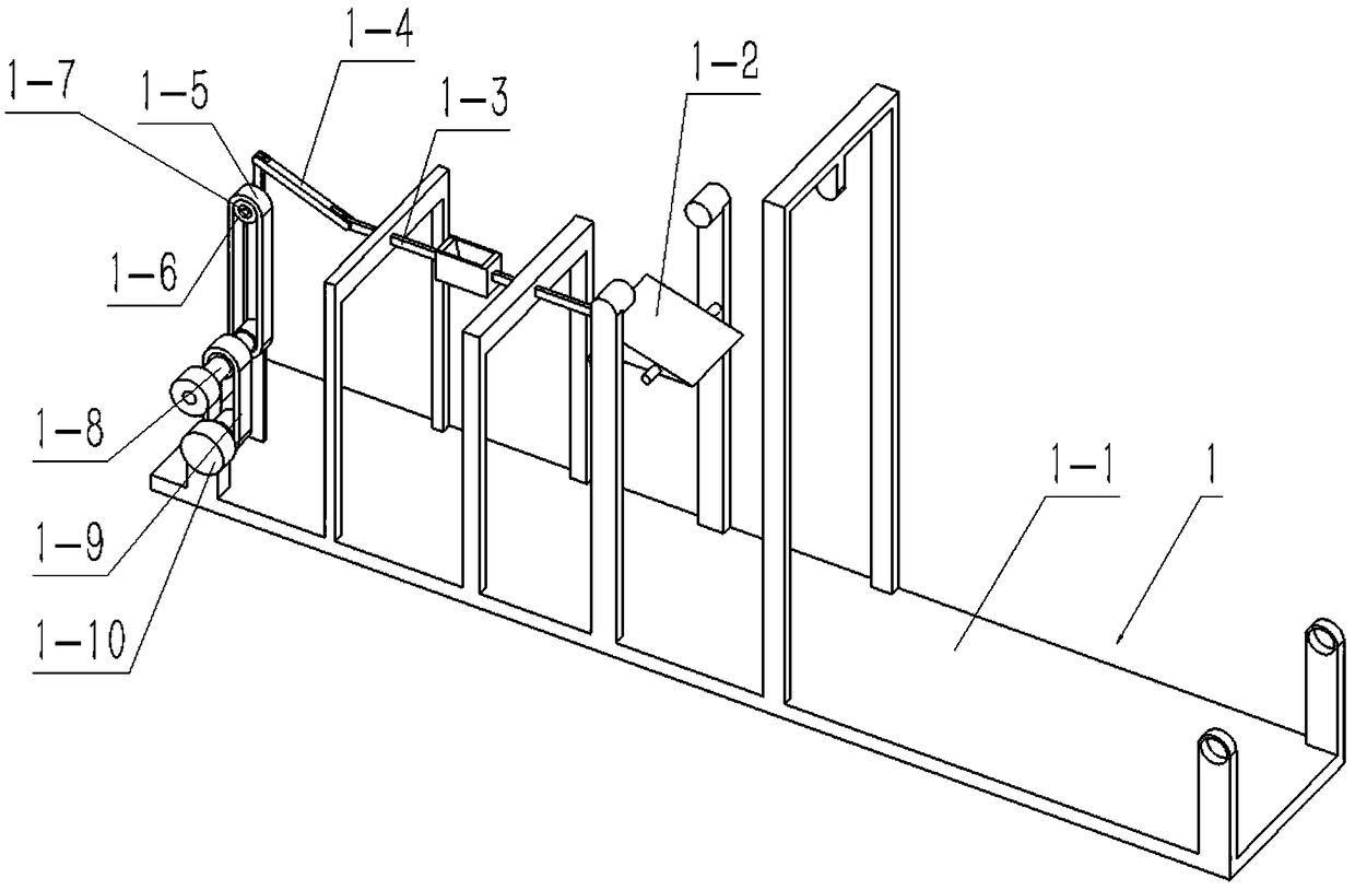
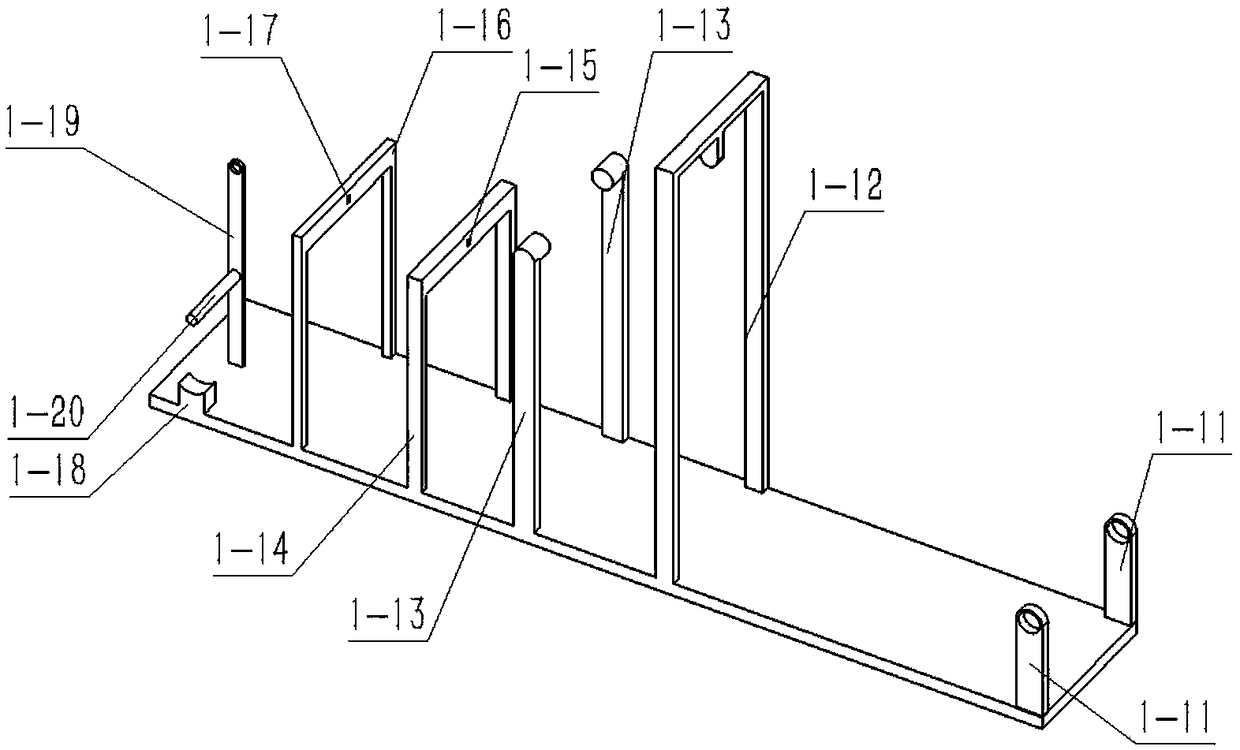
[0042] Combine below Figure 1-23 This embodiment will be described. This embodiment will further explain Embodiment 1. The support frame assembly 1 includes a support plate main body 1-1, an intermittent push plate 1-2, a driving push rod 1-3, and a middle connecting rod 1- 4. Drive belt 1-5, drive pulley Ⅰ 1-6, rocker 1-7, mid-end drive shaft 1-8, input belt 1-9, motor 1-10, two right hinged plates 1-11, Counterweight articulated frame 1-12, feeding end articulated frame 1-13, carriage Ⅰ1-14, rectangular sliding hole Ⅰ1-15, sliding frame Ⅱ1-16, rectangular sliding hole Ⅱ1-17, frame 1-18, Left hinge rod 1-19, middle end rod 1-20, intermittent push pedal body 1-21, four side wall sliding columns 1-22, push pedal connecting rod 1-23, push pedal outer frame 1-24, driving push Rod body 1-25, driving push rod terminal 1-26, middle drive shaft body 1-27, rear pulley 1-28, middle pulley 1-29 and front pulley 1-30, two right sides Hinged plates 1-11 are respectively fixedly connect...

specific Embodiment approach 3

[0043] Combine below Figure 1-23 Describe this embodiment, this embodiment will further explain Embodiment 1, the conveyor belt assembly 2 includes a conveyor belt body 2-1, a right end roller 2-2, a right end roller pulley 2-3, a left end roller 2-4, Two fixed plates 2-5, hinged posts 2-6 and upper connecting rods 2-7, the left end roller 2-4 and the right end roller 2-2 are respectively rotated and connected to the left and right ends of the two fixed plates 2-5, and the hinged posts The front and rear ends of 2-6 are respectively hingedly connected between the two fixing plates 2-5, the upper connecting rod 2-7 is fixedly connected to the middle end of the hinged column 2-6, and the left and right ends of the conveyor belt body 2-1 are respectively The interference fit is connected on the left end roller 2-4 and the right end roller 2-2, the right end roller belt pulley 2-3 is fixedly connected to the front end of the right end roller 2-2, and the front and rear ends of th...


PUM


Abstract

The invention relates to a transport device for medical wastes, in particular to a transport device for medical wastes of a surgery department. The waste transport rate can be changed; through changein mass of a fixing balancing weight, the feeding rate is changed; a vibration balancing terminal is provided, and can be used for balancing mechanical vibration; the transport device comprises a support assembly, a conveyer belt assembly, a balancing weight clamping assembly, a tapered slide rod, a feeding end, a vibration balancing terminal and a rotational band; the front and rear ends of a right end roller can be connected between two right side hinged plates conveniently and rotatably, and the left and right ends of the rotational band can be connected between a right end roller belt wheel and a front end belt wheel in a interference fit manner conveniently; the upper end of an upper side hinged rod can be hinged and connected with a balancing weight hinged frame conveniently, and theupper end of an upper end connecting bar can be hinged and connected with the interior of a hinged hollow-out groove conveniently; the upper end of a tapered slide rod body can be fixedly connected with the middle end of the lower end face of a balancing weight push rod conveniently, and the lower end of the tapered slide rod body is arranged at the inner end of a push plate outer frame; a plurality of side wall rollers can be arranged between the push plate outer frame and a driving push rod terminal conveniently.

Description

technical field [0001] The invention relates to a transport device for medical waste, more specifically to a transport device for trauma department medical waste. Background technique [0002] For example, the patent number is CN201610188557.1, a new type of garbage transportation device, including a car body, an upper cover plate, a connecting rod, a hydraulic rod, and an engine energy recovery device. The above cover is connected, one end of the hydraulic rod is connected with one of the connecting rods, and the other end is hinged on the car body; the garbage transport device is driven by the engine, and the engine energy recovery device is used to recover the heat of the engine exhaust, but the invention The disadvantage is that there is no way to change the rate at which garbage can be transported, which in turn reduces the rate of garbage disposal. Contents of the invention [0003] The purpose of the present invention is to provide a transportation device for traum...

Claims


Application Information

Patent Timeline
Patent Type & Authority Applications(China)
IPC IPC(8): B65G47/16B65G21/00
CPCB65G21/00B65G47/16
Inventor 郑涵
Owner 吴凯
Why Eureka
Try Eureka