Floating positioning and torque transmission structure of turbine guide device

A turbine guide, floating positioning technology, applied in the direction of machine/engine, stator, engine components, etc., can solve problems such as increasing structural complexity, and achieve the effect of eliminating thermal stress problems, reducing self-locking flow, and reducing expansion and deformation constraints

Active Publication Date: 2019-03-01
INST OF ENGINEERING THERMOPHYSICS - CHINESE ACAD OF SCI
View PDF7 Cites 4 Cited by
  • Summary
  • Abstract
  • Description
  • Claims
  • Application Information

AI Technical Summary

Problems solved by technology

However, the rim sealing structure proposed in the past often increases the complexity of the structure

Method used


Image

  • Floating positioning and torque transmission structure of turbine guide device
  • Floating positioning and torque transmission structure of turbine guide device

Examples


Embodiment Construction

[0019] The present invention will be further described in detail below in conjunction with the examples, the following examples are explanations of the present invention and the present invention is not limited to the following examples.

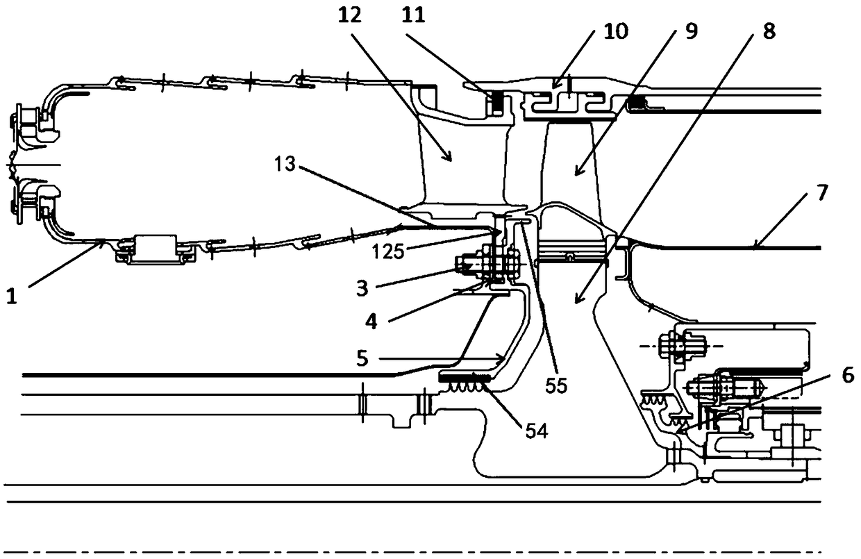
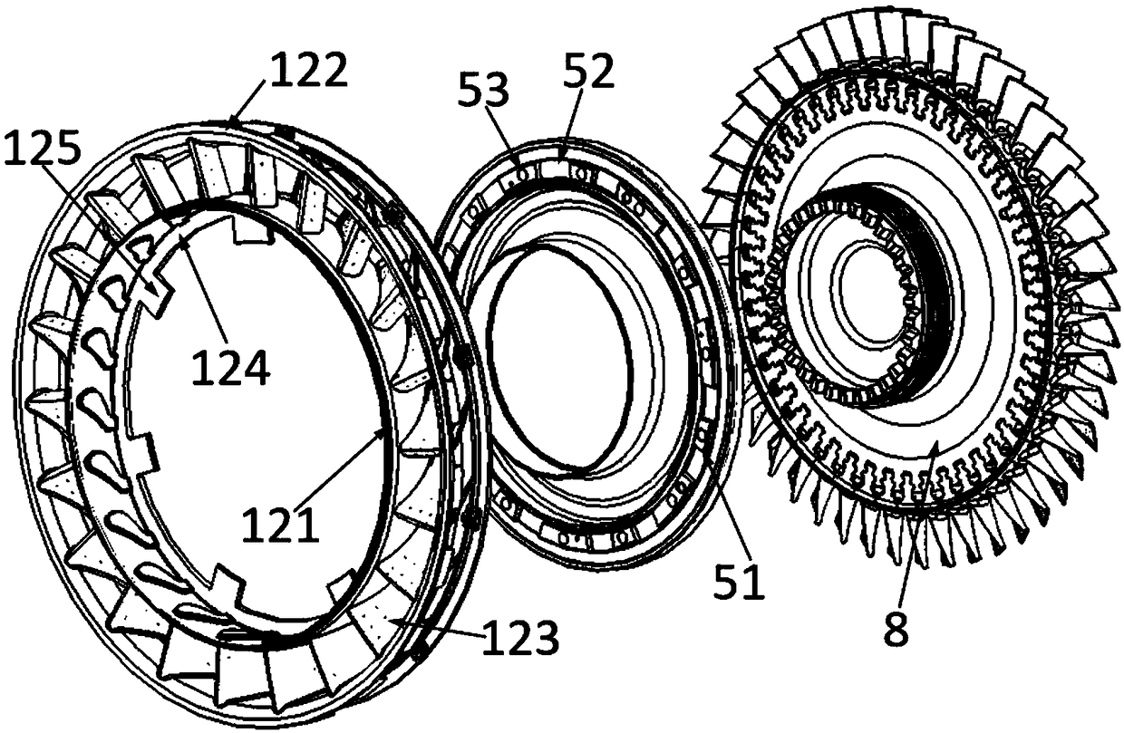
[0020] Such as figure 1 , 2 As shown, this embodiment is a design scheme of applying the floating positioning and torsion transmission structure of the turbine guider of the present invention in the downstream of an aeroengine combustion chamber. In this embodiment, the high-pressure turbine guide 12 and the high-pressure turbine rotor are sequentially arranged downstream of the combustor flame tube 1, and the high-pressure turbine rotor includes a high-pressure turbine disk 8 and high-pressure turbine rotor blades 9 arranged on the peripheral edge of the high-pressure turbine disk 8 The high-pressure turbine guide 12 is arranged axially upstream of the high-pressure turbine rotor blades 9 , and the upstream of the high-pressure turbine dis...


PUM


Abstract

The invention relates to a floating positioning and torque transmission structure of a turbine guide device, and is applicable to the field of ground combustion gas turbines, aero-engines and the like. An air baffle structure capable of sealing a rim of a turbine rotor blade is added to a front cavity of a turbine disk, a positioning rib structure is arranged on the air baffle structure, a floating positioning bulge is arranged on the turbine guide device in a matched manner, floating positioning and torque transmission of the turbine guide device are realized by the aid of the positioning riband floating positioning bulge structure, the expansion deformation constraint of the turbine guide device in the hot-state working environment is reduced to the maximum extent, and the hot stress ofthe guide device is reduced. The structure has great engineering application significance in prolonging of the life of the high-pressure turbine guide device of a ground combustion gas turbine or anaero-engine. Compared with traditional high-pressure turbine guide device structures and turbine disk front cavity baffle structures, the structure has the advantages that through the ingenious structural design, centered torque transmission of the high-pressure turbine guide device and high-efficiency rim sealing of rotor and stator end areas of a high-pressure turbine can be realized.

Description

technical field [0001] The invention belongs to the technical fields of ground gas turbines, aero-engines, etc., and relates to a floating positioning and torsion transmission structure of a high-pressure turbine guide. Using the combined structure of the turbine disk front gas baffle and the guide floating positioning protrusion, the turbine guider is finally realized. The function of free floating of the guider in the state of thermal expansion, positioning and torque transmission, and sealing of the rim of the front chamber of the turbine disk. Background technique [0002] The thermal stress release problem of the turbine guider after thermal expansion under high temperature environment, and the sealing problem of the turbine guider and the rotor rim are engineering problems with important practical significance in the fields of gas turbines and aeroengines. In the previous structural design of gas turbines and aero-engines, the structural design of the stress release of...

Claims


Application Information

Patent Timeline
Patent Type & Authority Applications(China)
IPC IPC(8): F01D5/02F01D9/04F01D11/00F01D25/24
CPCF01D5/02F01D9/041F01D11/00F01D25/246
Inventor 杜强刘军柳光王沛刘红蕊廉曾妍蒋文婷高金海冯引利徐庆宗肖向涛王若楠张帆
Owner INST OF ENGINEERING THERMOPHYSICS - CHINESE ACAD OF SCI
Why Eureka
Try Eureka