A two-stage high temperature condensation heat recovery heat pump system

A high-temperature condensation and heat pump system technology, which is applied in the field of condensation heat recovery heat pump and double-stage high-temperature condensation heat recovery heat pump system, can solve the problems of large irreversible loss of the system, large temperature difference between cold and heat of the condensing evaporator, and poor adjustability. The contradiction between heat supply and demand, ensuring the heating temperature and the effect of heat supply

Active Publication Date: 2021-08-27
ZHONGYE-CHANGTIAN INT ENG CO LTD
View PDF0 Cites 0 Cited by
  • Summary
  • Abstract
  • Description
  • Claims
  • Application Information

AI Technical Summary

Problems solved by technology

However, this condensation heat recovery method is limited by the cooling capacity, and the heat recovery capacity is limited, only about 25% of the condensation heat, and the temperature for preparing hot water is also low
[0004] And the heat pump system that supplies cooling and heating at the same time, whether it is a refrigeration heat pump system in the form of single-stage compression, cascade or intercooling two-stage compression, when these heat pump systems recover the heat of condensation, due to these refrigeration heat pumps The heating capacity of the system is greater than its cooling capacity, which limits its application to occasions where the heat supply is greater than the cooling capacity in summer, and the heat recovery is limited by the cooling capacity, so the adjustability is poor
These heat pump systems do not have the ability to produce hot water during transitional seasons when there is no cooling demand
[0005] In addition, although the cascade refrigeration system has the advantages of low pressure ratio and high volumetric efficiency, due to the use of non-azeotropic mixed refrigerants and complex heat exchangers, the exhaust pressure of the compressor is high.
Due to the large temperature difference between cold and hot of the condensing evaporator, the irreversible loss of the system is relatively large
As mentioned above, since the heating capacity of these systems is greater than the cooling capacity of the unit and the adjustment of heating capacity is poor, the scope of use of these systems is limited.

Method used


Image

  • A two-stage high temperature condensation heat recovery heat pump system

Examples


Embodiment 1

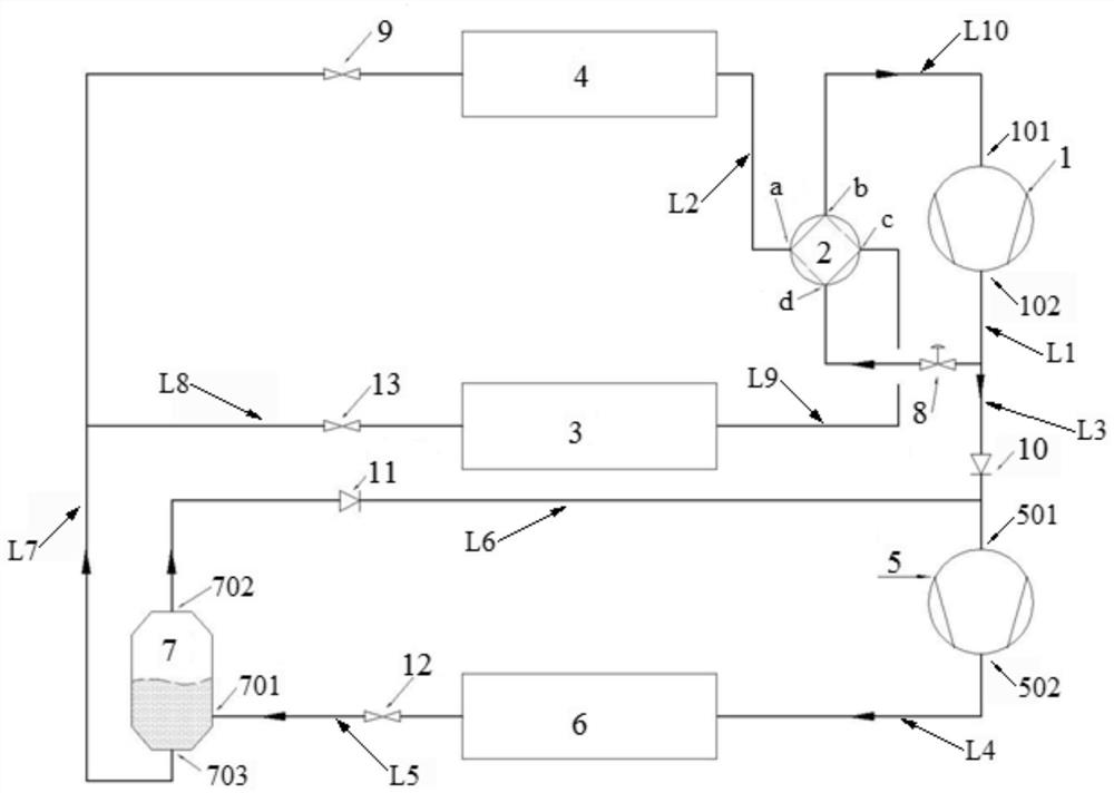
[0060] Such as figure 1 As shown, a two-stage high-temperature condensation heat recovery heat pump system includes a low-pressure compressor 1, a four-way valve 2, an indoor heat exchanger 3, an outdoor heat exchanger 4, a high-pressure compressor 5, a high-temperature water heater 6, and a gas-liquid Separator 7. Wherein, the first pipeline L1 drawn from the discharge port 102 of the low-pressure compressor 1 is connected to the port d of the four-way valve 2 . The a port of the four-way valve 2 is connected to one end of the outdoor heat exchanger 4 via the second pipeline L2. The third pipeline L3 branched from the first pipeline L1 is connected to the suction port 501 of the high-pressure compressor 5 . The exhaust port 502 of the high-pressure compressor 5 is connected to the inlet of the high-temperature water heater 6 via a fourth pipeline L4. The fifth pipeline L5 drawn from the outlet of the high-temperature water heater 6 is connected to the inlet 701 of the gas-...

Embodiment 2

[0072] Under summer working conditions, the two-stage high-temperature condensation heat recovery heat pump system of the present invention is used as a summer refrigeration cycle system to realize partial high-temperature condensation heat recovery working conditions: the first throttle valve 9 is fully open, the normally open solenoid valve 8 is not powered, and the low-pressure compressor One way of the exhaust gas of 1 flows to the outdoor heat exchanger 4 to condense through the solenoid valve 8, the d end of the four-way valve 2, and the a end of the four-way valve 2; the other way flows through the first one-way valve 10 to the high-pressure compressor Compressed again in 5, the exhaust gas from high-pressure compressor 5 is condensed in high-temperature water heater 6, and the liquid working medium discharged from high-temperature water heater 6 is throttled by second throttle valve 12, flashed and separated in gas-liquid separator 7, and saturated The gas working medium ...

Embodiment 3

[0074] In summer working conditions, the two-stage high-temperature condensation heat recovery heat pump system of the present invention is used as a summer refrigeration cycle system to realize full-heat high-temperature condensation heat recovery working conditions: the normally open solenoid valve 8 is energized and closed, the first throttle valve 9 is closed, and the low-pressure compressor The exhaust of 1 flows through the first one-way valve 10 to the high-pressure compressor 5 to be compressed again, the exhaust of the high-pressure compressor 5 is condensed in the high-temperature water heater 6, and the liquid working medium discharged from the high-temperature water heater 6 passes through the second throttle valve 12 After throttling, it flashes and separates in the gas-liquid separator 7, and the saturated gas working medium flows through the second check valve 11 and returns to the high-pressure compressor 5, and the saturated liquid working medium is throttled by...


PUM


Abstract

A two-stage high-temperature condensation heat recovery heat pump system, the system includes a low-pressure compressor (1), a four-way valve (2), an indoor heat exchanger (3), an outdoor heat exchanger (4), and a high-pressure compressor (5) , high-temperature water heater (6), gas-liquid separator (7). The heat pump system can meet different needs under various working conditions. The high-temperature condensation heat recovered in summer can meet the requirements of heating temperature and heating capacity, and the recovery volume can be adjusted from 0 to 100; Separately produce high and low temperature domestic hot water; in winter, it can solve the heat supply and demand contradiction of air source heat pump heating and ensure the demand for high temperature domestic hot water.

Description

technical field [0001] The invention relates to a condensation heat recovery heat pump of an air-conditioning system, in particular to a two-stage high-temperature condensation heat recovery heat pump system, which belongs to the fields of building air conditioning and heating energy utilization. Background technique [0002] The existing condensation heat recovery system mainly includes: a heat pump air conditioner under three modes of total condensation heat recovery, partial condensation heat recovery and composite condensation heat recovery with a heat exchanger installed on the compressor exhaust pipe in front of the outdoor condenser; Two-stage compression refrigerating heat pump cycle, a heat pump system that realizes combined cooling and heating through two-stage compression, can recover all the condensation heat in summer, and can meet the demand for heating capacity and heating temperature in winter, but it is only applicable when the heat supply in summer is greate...

Claims


Application Information

Patent Timeline
Patent Type & Authority Patents(China)
IPC IPC(8): F25B13/00F25B41/20F25B49/02
CPCF25B13/00F25B49/02F25B41/40F25B41/20Y02B30/52
Inventor 段超龙年卫琦刘雄乐文毅冯晓峰刘再新
Owner ZHONGYE-CHANGTIAN INT ENG CO LTD
Why Eureka
Try Eureka