Phase-change heat storage system with stirrer

A phase change heat storage and agitator technology, which is applied to heat storage equipment, heat exchanger types, indirect heat exchangers, etc., can solve the problems of insufficient utilization of phase change materials, increased heat storage costs, and low heat storage efficiency. Achieve the effect of improving utilization rate and heat storage efficiency, reducing heat storage cost and improving stirring quality

Pending Publication Date: 2019-03-01
TIANJIN BINHAI ENERGY STORAGE TECH
View PDF0 Cites 0 Cited by
  • Summary
  • Abstract
  • Description
  • Claims
  • Application Information

AI Technical Summary

Problems solved by technology

The heat storage and utilization of phase change materials are divided into three processes: heating, heat storage, and heat release. The change state of phase change materials is: solid-liquid-solid phase change process. Material crystals are precipitated and precipitated. After multiple phase change processes, some crystals at the bottom of the heat storage equipment cannot be liquefied, resulting in insufficient utilization of phase change materials, low heat storage efficiency, and increased heat storage costs.

Method used


Image

  • Phase-change heat storage system with stirrer
  • Phase-change heat storage system with stirrer
  • Phase-change heat storage system with stirrer

Examples


Embodiment 1

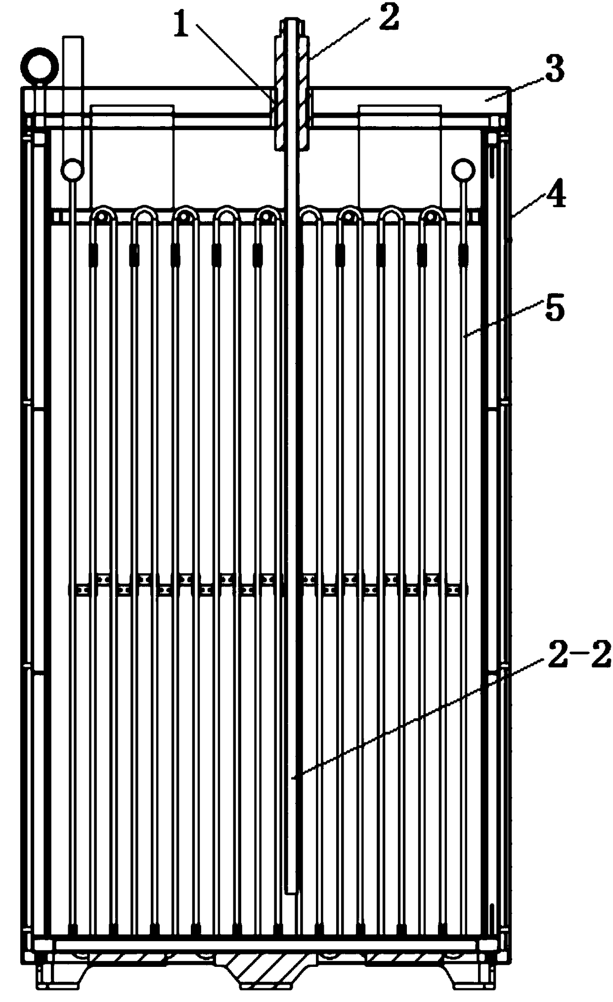
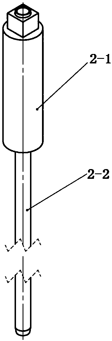
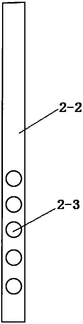
[0037] The phase change heat storage system with agitator includes a heat storage tank 4, an upper cover 3 and a heat exchanger 5. The heat storage tank 4 is a barrel-shaped structure with an open top, and an upper cover 3 is provided on the top. The heat exchanger 5 is arranged inside the heat storage tank 4, and the center of the upper cover 3 is provided with a through hole passing through the upper cover. The inner wall of the through hole is provided with threads, and a nitrogen pipe 2 is vertically arranged in the through hole. The nitrogen pipe 2 comprises an outer pipe 2-1 and an inner pipe 2-2;

[0038] The phase-change heat storage system with a stirrer of the present invention feeds high-pressure nitrogen gas into the bottom of the heat storage tank 4 through the nitrogen pipe 2, and blows the phase-change material solid deposited at the bottom of the heat storage tank 4 by the strong airflow formed by the high-pressure nitrogen gas, The floating and the upper liqui...

Embodiment 2

[0045] The phase change heat storage system with agitator includes a heat storage tank 4, an upper cover 3 and a heat exchanger 5. The heat storage tank 4 is a barrel-shaped structure with an open top, and an upper cover 3 is provided on the top. The heat exchanger 5 is arranged inside the heat storage tank 4, and the center of the upper cover 3 is provided with a through hole passing through the upper cover. The inner wall of the through hole is provided with threads, and a nitrogen pipe 2 is vertically arranged in the through hole. The nitrogen pipe 2 comprises an outer pipe 2-1 and an inner pipe 2-2;

[0046] The phase-change heat storage system with a stirrer of the present invention feeds high-pressure nitrogen gas into the bottom of the heat storage tank 4 through the nitrogen pipe 2, and blows the phase-change material solid deposited at the bottom of the heat storage tank 4 by the strong airflow formed by the high-pressure nitrogen gas, The floating and the upper liqui...

Embodiment 3

[0054] The phase change heat storage system with agitator includes a heat storage tank 4, an upper cover 3 and a heat exchanger 5. The heat storage tank 4 is a barrel-shaped structure with an open top, and an upper cover 3 is provided on the top. The heat exchanger 5 is arranged inside the heat storage tank 4, and the center of the upper cover 3 is provided with a through hole passing through the upper cover. The inner wall of the through hole is provided with threads, and a nitrogen pipe 2 is vertically arranged in the through hole. The nitrogen pipe 2 comprises an outer pipe 2-1 and an inner pipe 2-2;

[0055] The phase-change heat storage system with a stirrer of the present invention feeds high-pressure nitrogen gas into the bottom of the heat storage tank 4 through the nitrogen pipe 2, and blows the phase-change material solid deposited at the bottom of the heat storage tank 4 by the strong airflow formed by the high-pressure nitrogen gas, The floating and the upper liqui...


PUM

PropertyMeasurementUnit
Outer diameteraaaaaaaaaa
Wall thicknessaaaaaaaaaa

Abstract

The invention discloses a phase-change heat storage system with a stirrer. The phase-change heat storage system comprises a heat storage tank, an upper cover and a heat exchanger, wherein the heat storage tank is of a barrel-shaped structure with an opening in the top end, an upper cover is arranged at the top of the heat storage tank, the heat exchanger is arranged in the heat storage tank, a through hole penetrating through the upper cover is formed in the center of the upper cover, threads are formed in the inner wall of the through hole, a nitrogen pipe is vertically arranged in the through hole, the nitrogen pipe comprises an outer pipe and an inner pipe, threads are arranged on the outer wall of the outer pipe, the inner pipe is arranged in the outer pipe and is coaxial with the outer pipe, a nut is arranged at the top end of the inner pipe, the bottom surface of the nut is lapped on the top surface of the outer pipe. High-pressure nitrogen is introduced into the bottom of the heat storage tank through the nitrogen pipe, solid blowing is carried out on the phase-change material deposited at the bottom of the heat storage tank through strong airflow formed by high-pressure nitrogen, so that the phase-change material can upward floating and are fully combined with the upper liquid phase and liquefied, the problem that solid precipitates are not dissolved is solved, the utilization rate of the phase change material and the heat storage efficiency are improved, and the heat storage cost is reduced.

Description

technical field [0001] The invention belongs to the field of heat storage of phase change materials, in particular to a phase change heat storage system with a stirrer. Background technique [0002] Due to the rapid economic development, our country is facing more and more pressure from energy shortage and environmental pollution. At this stage, my country is in the accelerated period of industrialization development, and the contradiction between energy supply and demand is becoming increasingly prominent. The energy production and consumption structure dominated by coal is seriously damaging the ecological environment of our country. In order to realize the green transformation of energy structure and accelerate the transformation of energy development mode, we must find ways to reduce greenhouse gas emissions and improve the efficiency of energy development, processing and conversion. [0003] The peak-to-valley difference between day and night in my country's power gri...

Claims


Application Information

Patent Timeline
IPC IPC(8): F28D20/02
CPCF28D20/021Y02E60/14
Inventor 官景栋李建丽
Owner TIANJIN BINHAI ENERGY STORAGE TECH
Why Eureka
Try Eureka