Automatic timing viscosity meter

An automatic timing and viscometer technology, which is applied in the field of mechanical devices, can solve the problems of inaccurate liquid viscosity measurement, unreasonable viscometer base structure, and unreasonable placement of liquid cups, etc., to achieve a simple and strong promotion of viscosity measurement methods The effect of value, simple structure

Pending Publication Date: 2019-03-01
KUNMING UNIV OF SCI & TECH
View PDF6 Cites 4 Cited by
  • Summary
  • Abstract
  • Description
  • Claims
  • Application Information

AI Technical Summary

Problems solved by technology

However, there are still the following deficiencies: 1) When measuring the kinematic viscosity of a liquid, manual timing is required, and it is easy to cause inaccurate measurement of the viscosity of the liquid due to errors in manual timing; 2) Before performing viscosity measurement, the When the liquid storage cup is filled with the liquid to be tested, it is necessary to block the outlet at the lower end of the liquid storage cup by hand, which is dangerous and the operability is not strong; 3) The unreasonable structure of the viscometer base results in heavy mass ;4) There is no positioning groove for the liquid cup on the base itself, resulting in unreasonable placement of the liquid cup

Method used


Image

  • Automatic timing viscosity meter
  • Automatic timing viscosity meter
  • Automatic timing viscosity meter

Examples


Embodiment 1

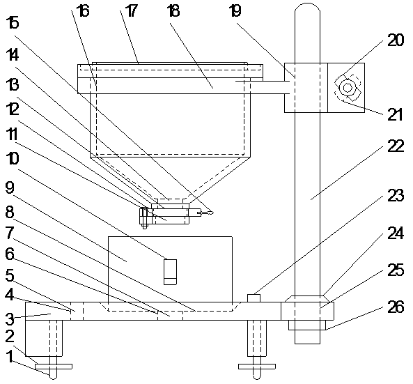
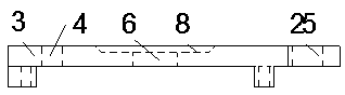
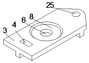
[0021] Embodiment 1: as Figure 1-7 As shown, an automatic timing viscometer includes a foot screw 1, a hand wheel 2, a platform base 3, a timing display installation groove 4, a timing display 5, a pressure sensor installation groove 6, a pressure sensor 7, a filling cup positioning groove 8, Filling Cup 9, Filling Cup Handle 10, Auxiliary Outlet 11, Bolt 12, Stop Plate 13, Main Outlet 14, Stop Plate Handle 15, Cross Arm Large Round Hole 16, Liquid Storage Cup 17 , cross arm 18, cross arm small round hole 19, lock bolt 20, lock nut 21, support pole 22, spirit level 23, rubber pad 24, support pole mounting hole 25, support pole nut 26; hand wheel 2 Fixed on the foot screw 1, the foot screw 1 is connected to the platform base 3, the timing display 5 is connected to the pressure sensor 7, the timing display 5 is installed in the timing display installation groove 4 on the platform base 3, and the pressure sensor 7 is installed on the platform base 3 in the pressure sensor insta...


PUM


Abstract

The invention relates to an automatic timing viscosity meter and belongs to the technical field of mechanical devices. The automatic timing viscosity meter comprises a support leg screw, a hand wheel,a platform base, a timing display mounting groove, a timing display, a pressure sensor mounting groove, a pressure sensor, a containing cup positioning slot, a containing cup, a containing cup handle, an auxiliary discharging port, a bolt, a check plate, a main discharging port, a check plate handle, a cross arm large round hole, a liquid to be measured storage cup, a cross arm, a cross arm smallround hole, a locking bolt, a support stand rod, a level gauge, a rubber cushion, a support stand rod mounting hole and a support stand rod screw. By automatically and accurately recording the time interval between that liquid to be measured starts to flow out of the main discharging port and the auxiliary discharging port at the lower end of the liquid to be measured storage cup and that the liquid to be measured completely flows out, the automatic timing viscosity meter can avoid the problem of inaccurate liquid viscosity measurement due to manual timing errors.

Description

technical field [0001] The invention relates to an automatic timing viscometer, which is especially suitable for viscometers that need to measure the kinematic viscosity of liquid more accurately, and belongs to the technical field of mechanical devices. Background technique [0002] The study of fluid mechanics of liquids is gradually increasing, and the viscosity of fluids is a key parameter in the study of fluids, which brings demand for the use of fluid viscometers, especially viscometers that are simple and accurate to measure fluid viscosity. CN106404603 A provides a viscometer with simple structure, easy operation, good stability and convenient viscosity measurement. However, there are still the following deficiencies: 1) When measuring the kinematic viscosity of a liquid, manual timing is required, and it is easy to cause inaccurate measurement of the viscosity of the liquid due to errors in manual timing; 2) Before performing viscosity measurement, the When the liq...

Claims


Application Information

Patent Timeline
Patent Type & Authority Applications(China)
IPC IPC(8): G01N11/06
CPCG01N11/06
Inventor 董为民漆昌元孙东明许平尹红
Owner KUNMING UNIV OF SCI & TECH
Why Eureka
Try Eureka