
Swing type wave energy power generation buoy

A wave energy and swing type technology is applied in the field of swing type wave energy power generation buoys, which can solve the problems of driving power generation devices, single function, rigid structure, etc., and achieve the effects of improving power generation efficiency, improving work efficiency, and increasing input rotational speed.

Pending Publication Date: 2019-03-01
LUDONG UNIVERSITY
View PDF6 Cites 7 Cited by
  • Summary
  • Abstract
  • Description
  • Claims
  • Application Information

AI Technical Summary

Problems solved by technology

[0002] Wave energy refers to the kinetic energy and potential energy of ocean surface waves. It is widely used in ocean power generation. Electric energy is one of the most common energy sources. Among them, buoys use wave energy to generate electricity. The existing buoys have rigid structures. , the function is single, under the impact of seawater, it is impossible to drive the power generation device thr

Method used


Image

  • Swing type wave energy power generation buoy
  • Swing type wave energy power generation buoy
  • Swing type wave energy power generation buoy

Examples


Example Embodiment

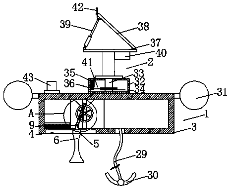
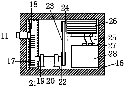
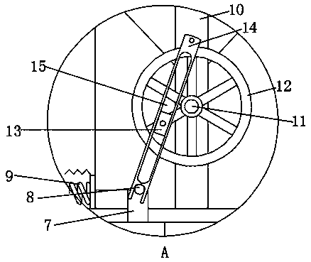
[0020] Such as Figure 1-4 As shown, this specific embodiment adopts the following technical solution: a swinging wave energy power generation buoy, including a first power generation mechanism 1 and a second power generation mechanism 2, and the top of the first power generation mechanism 1 is provided with a second power generation mechanism 2, The first power generation mechanism 1 is composed of a suspension box 3, a swing chute 4, a swing slider 5, a toggle plate 6, a connecting block 7, a swing shaft 8, a return spring 9, a support column 10, a first rotating shaft 11, and a swing wheel 12. Slide block 13, push rod 14, push chute 15, transmission box 16, gear box 17, first gear 18, bearing seat 19, second shaft 20, second gear 21, first pulley 22, first belt 23. The second pulley 24, the fixed base 25, the generator 26, the wire 27, the storage battery 28, the fixed steel cable 29 and the fixed anchor 30 are composed. The bottom of the suspension box 3 is excavated with a...


PUM


Abstract

The invention discloses a swing type wave energy power generation buoy. The swing type wave energy power generation buoy comprises a first power generation mechanism and a second power generation mechanism, wherein the second power generation mechanism is arranged on the top of the first power generation mechanism; the first power generation mechanism is composed of a suspension box, a swinging sliding groove, a swinging sliding block, a stirring plate, a connecting block, a swinging shaft, a reset spring, a supporting column, a first rotating shaft, a swinging wheel, a sliding block, a pushing rod, a pushing sliding groove, a transmission box, a gearbox and the like. According to the buoy, the stirring plate and the transmission box are arranged, so that under the impact action of the seawater, the stirring plate can be conveniently pushed to do reciprocating motion, and the wave energy can be used for driving the swinging wheel to rotate; the input rotating speed is increased throughthe transmission mechanism of the transmission box, and the working efficiency of the generator is improved; and a solar tracker and a control panel are arranged, so that the solar panel can always face the sun position, and therefore, the conversion rate of solar energy is improved, the power generation efficiency is improved, and the practicability of the buoy is improved.

Description

technical field [0001] The invention relates to the technical field of wave energy power generation, in particular to a swing type wave energy power generation buoy. Background technique [0002] Wave energy refers to the kinetic energy and potential energy of ocean surface waves. It is widely used in ocean power generation. Electric energy is one of the most common energy sources. Among them, buoys use wave energy to generate electricity. The existing buoys have rigid structures. , the function is single, under the impact of seawater, it is impossible to drive the power generation device through its reciprocating swinging seawater, and the working efficiency of the generator cannot be improved by increasing its input speed, and the power generation method is single, so that when the solar panel generates power, no It can always face the position of the sun, and the conversion rate of solar energy cannot be improved, and the power generation efficiency cannot be improved, wh...

Claims


Application Information

Patent Timeline
IPC IPC(8): H02S10/10H02S20/32F03B13/20B63B35/44
CPCH02S10/10H02S20/32F03B13/20B63B35/44B63B2035/4466B63B2035/4453Y02E10/50Y02E10/30
Inventor 石洪源尤再进钟超隋意王立杨
Owner LUDONG UNIVERSITY
Learn More