
Method of manufacturing an optical connection component

An optical connection and component technology, applied in the field of manufacturing optical connection components, can solve the problems of optical fiber mechanical reliability degradation and other problems

Active Publication Date: 2021-03-16
SUMITOMO ELECTRIC IND LTD
View PDF9 Cites 0 Cited by
  • Summary
  • Abstract
  • Description
  • Claims
  • Application Information

AI Technical Summary

Problems solved by technology

This Patent Document 1 discloses a case where a sharp bend is generated in the optical fiber when the optical fiber is attached obliquely with respect to the center line of the optical component body, which has the effect of generating a large deformation of the optical fiber in the sharply bent portion, so that the mechanical reliability of the optical fiber deteriorates problem, and disclosed that the deformation is removed by heating the sharply bent part in order to ensure the mechanical reliability of the optical fiber

Method used


Image

  • Method of manufacturing an optical connection component
  • Method of manufacturing an optical connection component
  • Method of manufacturing an optical connection component

Examples


Embodiment Construction

[0044] [Description of Embodiments of the Invention of the Present Application]

[0045] First, each aspect of the embodiments of the invention of the present application will be pointed out and described individually.

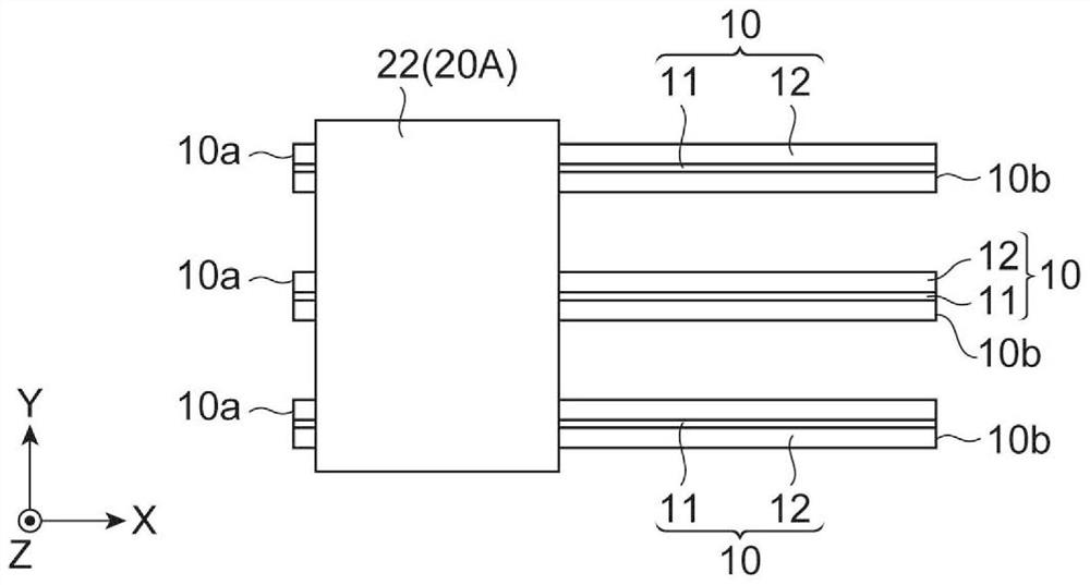
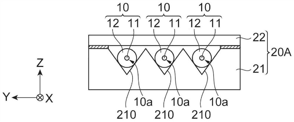
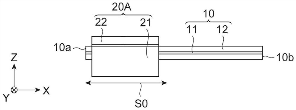
[0046] (1) In the method of manufacturing an optical connection part according to the present embodiment, an optical connection part including a bent optical fiber having a curved shape portion and an optical fiber fixing part attached to the bent optical fiber is manufactured. Specifically, as an aspect of this embodiment, the method includes at least a preliminary step, an installation step, a bending optical fiber manufacturing step, and a fixing step, and the bending optical fiber manufacturing step includes an elastic bending step and a heating step. In a preliminary step, an optical fiber made of silica-based glass is prepared, and a first optical fiber fixing member having a structure for restricting movement of the optical fiber in a direction perpendi...


PUM

PropertyMeasurementUnit
lengthaaaaaaaaaa
lengthaaaaaaaaaa
radiusaaaaaaaaaa

Abstract

This embodiment can reduce the height of an optical connection part including a bent optical fiber having a curved shape part and an optical fiber fixing part in a safer and more stable manner than the prior art. Before fixing the optical fiber fixing member to the bent optical fiber, forming and heating of the bent portion using the obliquely arranged optical fiber fixing member are repeated a plurality of times on the optical fiber to which the optical fiber fixing member is movably attached. During this time, the movement of the optical fiber and the heating of the bent portion may be alternately repeated to form a plurality of bent portions in which stress is released in the longitudinal direction of the optical fiber.

Description

technical field [0001] The present invention relates to a method of manufacturing an optical connection part including a bent optical fiber obtained by bending a part of an optical fiber made of quartz-based glass. Background technique [0002] As the size of optical components decreases, it is necessary to reduce the height of optical fibers used near the optical components (so that the height of optical fibers connected vertically to an electronic substrate or the like at one end decreases from the substrate). In order to reduce the height of the optical fiber, it is necessary to form a bent portion in the optical fiber. [0003] Patent Document 1 discloses an optical fiber component composed of an optical component body and an optical fiber, and configured such that the optical fiber is attached obliquely to form an angle (preferably 10° or more) with respect to the center line of the optical component body. This Patent Document 1 discloses a case where a sharp bend is g...

Claims


Application Information

Patent Timeline
Patent Type & Authority Patents(China)
IPC IPC(8): G02B6/02C03B37/15G02B6/46
CPCC03B37/15G02B6/3636G02B6/3833G02B2006/12119G02B6/3829C03B2205/67G02B6/3855
Inventor 金内靖臣佐佐木隆
Owner SUMITOMO ELECTRIC IND LTD
Learn More