
Alignment method, alignmenet apparatus, vacuum evaporation method and vacuum evaporation apparatus

A technology for alignment marks and detection methods, applied in vacuum evaporation coating, measuring devices, using optical devices, etc.

Active Publication Date: 2019-03-05
CANON TOKKI CORP
View PDF8 Cites 7 Cited by
  • Summary
  • Abstract
  • Description
  • Claims
  • Application Information

AI Technical Summary

Problems solved by technology

The organic layer and electrode metal layer of the organic electroluminescent display are manufactured by evaporating the vapor-deposited substance on the substrate through a mask forming a desired pixel pattern in a vacuum chamber, but in order to make the vapor-deposited substance in the desired The pattern is vapor deposited on the desired position on the substrate, and the position of the mask and the substrate must be precisely aligned before vapor deposition on the substrate

Method used


Image

  • Alignment method, alignmenet apparatus, vacuum evaporation method and vacuum evaporation apparatus
  • Alignment method, alignmenet apparatus, vacuum evaporation method and vacuum evaporation apparatus
  • Alignment method, alignmenet apparatus, vacuum evaporation method and vacuum evaporation apparatus

Examples


Embodiment Construction

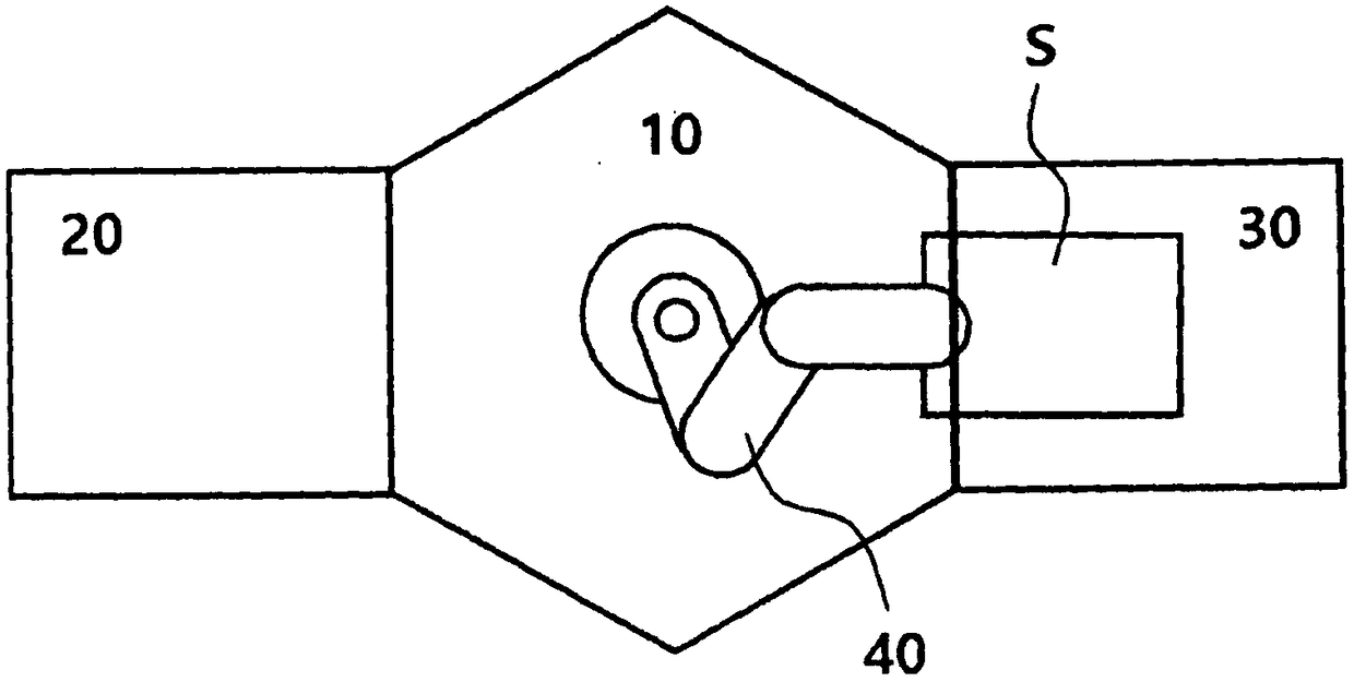
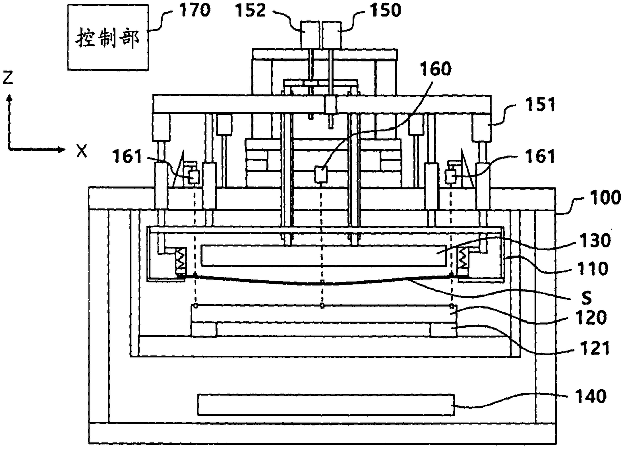
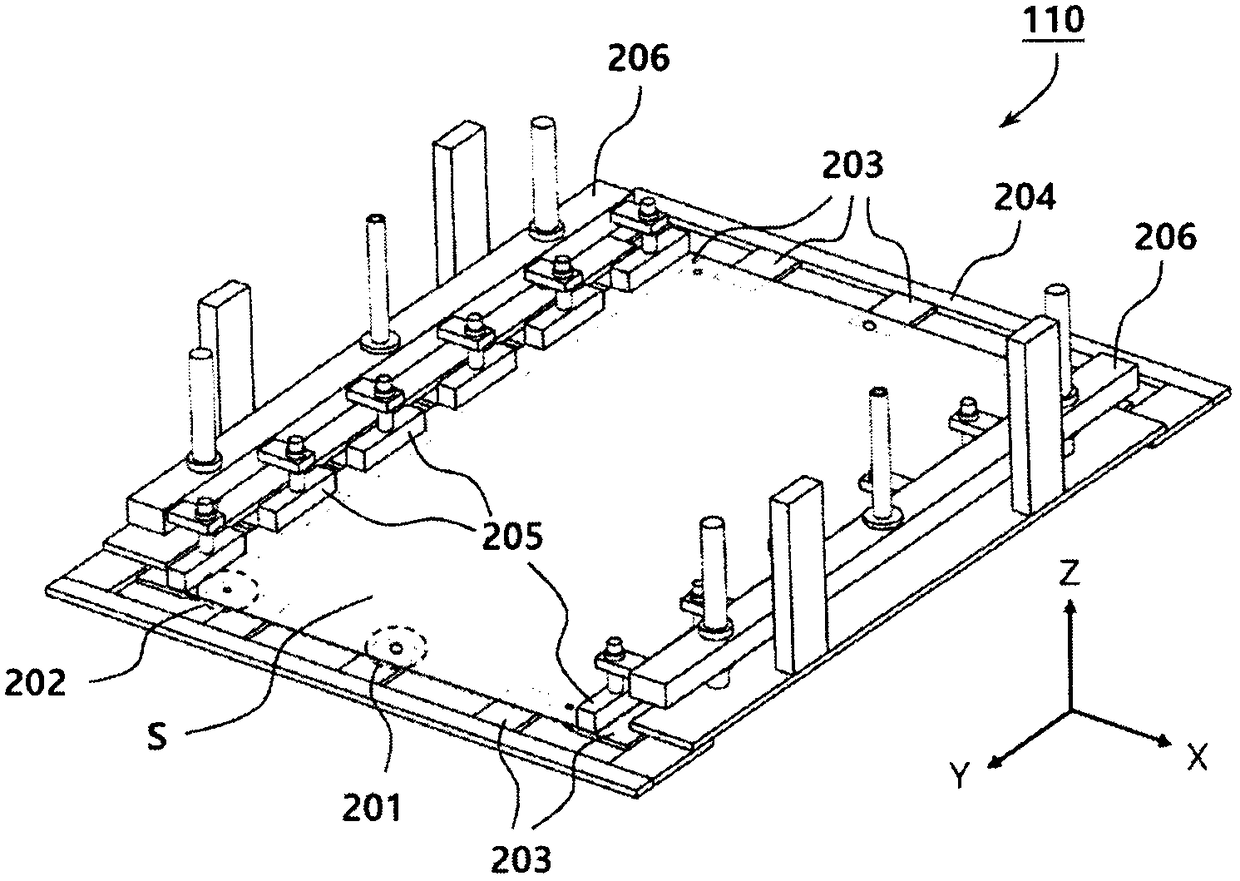
[0031] Hereinafter, embodiments of the present invention will be described in detail with reference to the drawings. The present invention can be modified variously, and can have various embodiments. Although specific examples are illustrated based on the drawings, the present invention is not limited to the specific examples, and it should be understood that all changes, equivalents, and substitutions included in the spirit and scope of the present invention are included.

[0032]The present invention relates to a film forming apparatus for forming a thin film on a substrate and a control method thereof, and particularly relates to a technology for high-precision conveyance and position adjustment of a substrate. The present invention can be preferably applied to an apparatus for forming a thin film (material layer) of a desired pattern by vacuum evaporation on the surface of a parallel plate substrate. Also, any material such as glass, resin, or metal can be selected as the...


PUM


Abstract

The present invention relates to an alignment mark detecting method for detecting an alignment mark formed on a substrate by using an optical device. The method includes the steps of: photographing the alignment mark by using the optical device to obtain image data; and comparing the obtained image data with a model image to detect the position of the alignment mark. The model image includes a first model image obtained by photographing the alignment mark in advance and a second model image created based on design data of the alignment mark. When the focus value of the image data obtained in the step of obtaining the image data is within a predetermined range including a peak value, a real image processing is performed, in which the obtained image data is compared with the first model image to detect the position of the alignment mark. When the focus value of the image data obtained in the step of obtaining the image data is out of the predetermined range, an artificial image processing is performed in which the obtained image data is compared with the second model image to detect the position of the alignment mark.

Description

technical field [0001] The present invention relates to an alignment method, an alignment device, a vacuum evaporation method, and a vacuum evaporation device, and in particular, relates to a process for highly precise bonding of a mask and a substrate in a vacuum evaporation process of an organic electroluminescent display device. Method and device for position alignment. Background technique [0002] Recently, organic electroluminescent displays have emerged as flat panel displays. As a self-luminous display, organic electroluminescent displays are superior to liquid crystal panel displays in terms of response speed, viewing angle, and thinner. They are rapidly replacing Existing LCD panel displays. In addition, its application fields are also widely distributed in automotive displays and the like. [0003] An organic electroluminescence display has a basic structure in which an organic substance layer that causes light emission is formed between two electrodes (cathode...

Claims


Application Information

Patent Timeline
IPC IPC(8): C23C14/04C23C14/24C23C14/50C23C14/54
CPCC23C14/042C23C14/24C23C14/50C23C14/54G01B11/00H01L21/67259H01L21/67282H01L21/68H10K71/00
Inventor 谷和宪长沼义人内田亘
Owner CANON TOKKI CORP
Learn More