Water energy cleaner

A cleaner and water energy technology, which is applied in public buildings, gymnasiums, building types, etc., can solve the problems of insufficient output torque and insufficient stability of the output force, achieve large output torque and improve the utilization rate of water energy resources. , The effect of high output force stability

Inactive Publication Date: 2019-03-05
NINGBO POOLSTAR POOL PROD CO LTD
View PDF7 Cites 5 Cited by
  • Summary
  • Abstract
  • Description
  • Claims
  • Application Information

AI Technical Summary

Problems solved by technology

[0007] However, in this prior art, the direction perpendicular to the water flow between the fan surface of the impeller blade and the water flow is achieved after the opposite blade is guided and rotated by 90°. Therefore, the hydraulic motor is limited by the structure of the blade, and the stability of the output force is insufficient. , The output torque is not enough, etc.

Method used


Image

  • Water energy cleaner
  • Water energy cleaner
  • Water energy cleaner

Examples


Embodiment 1

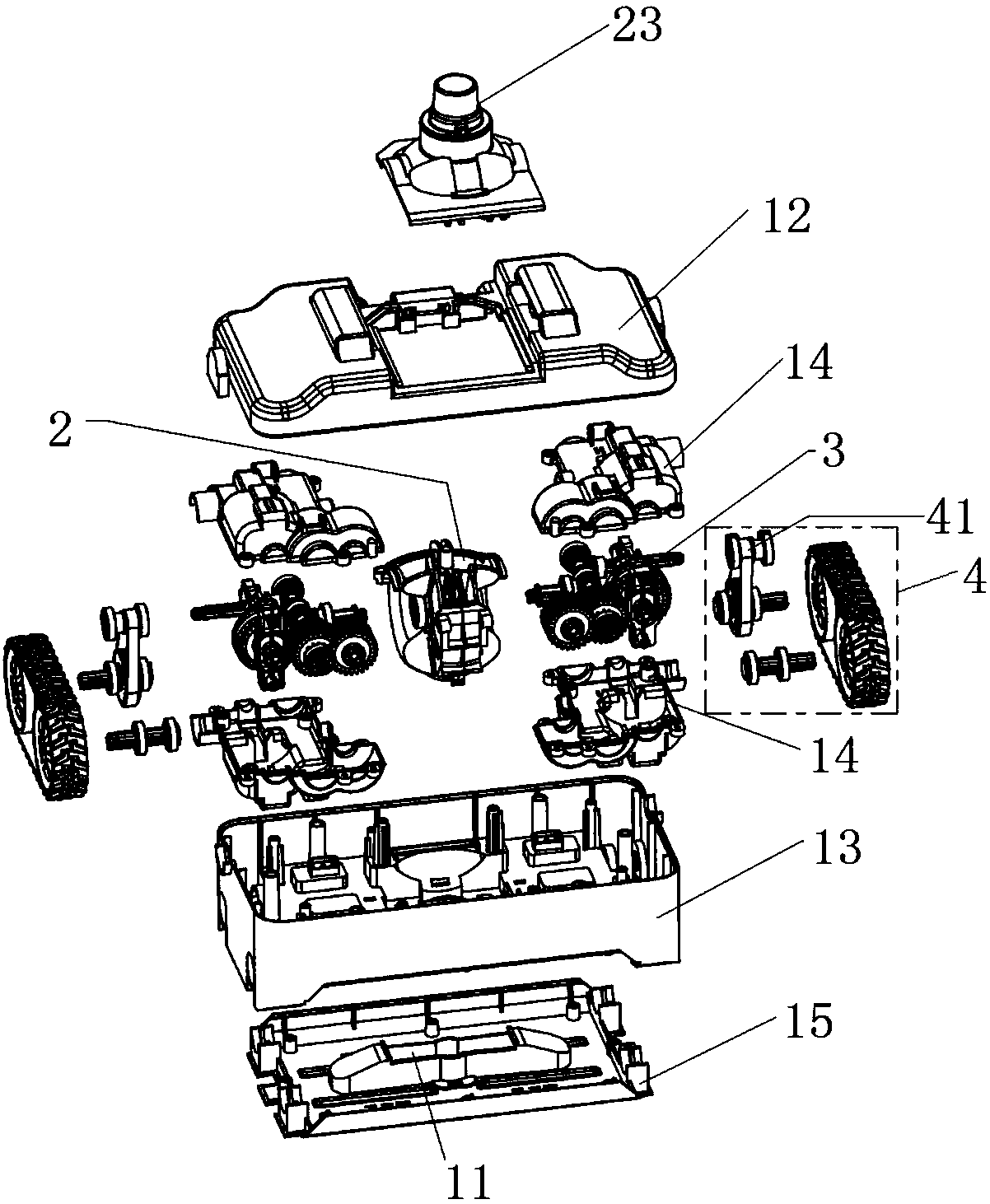
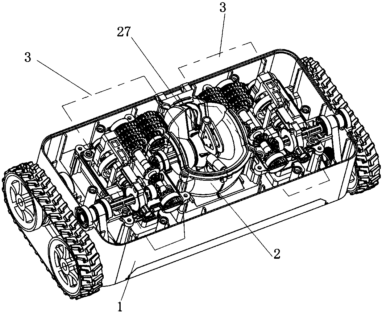
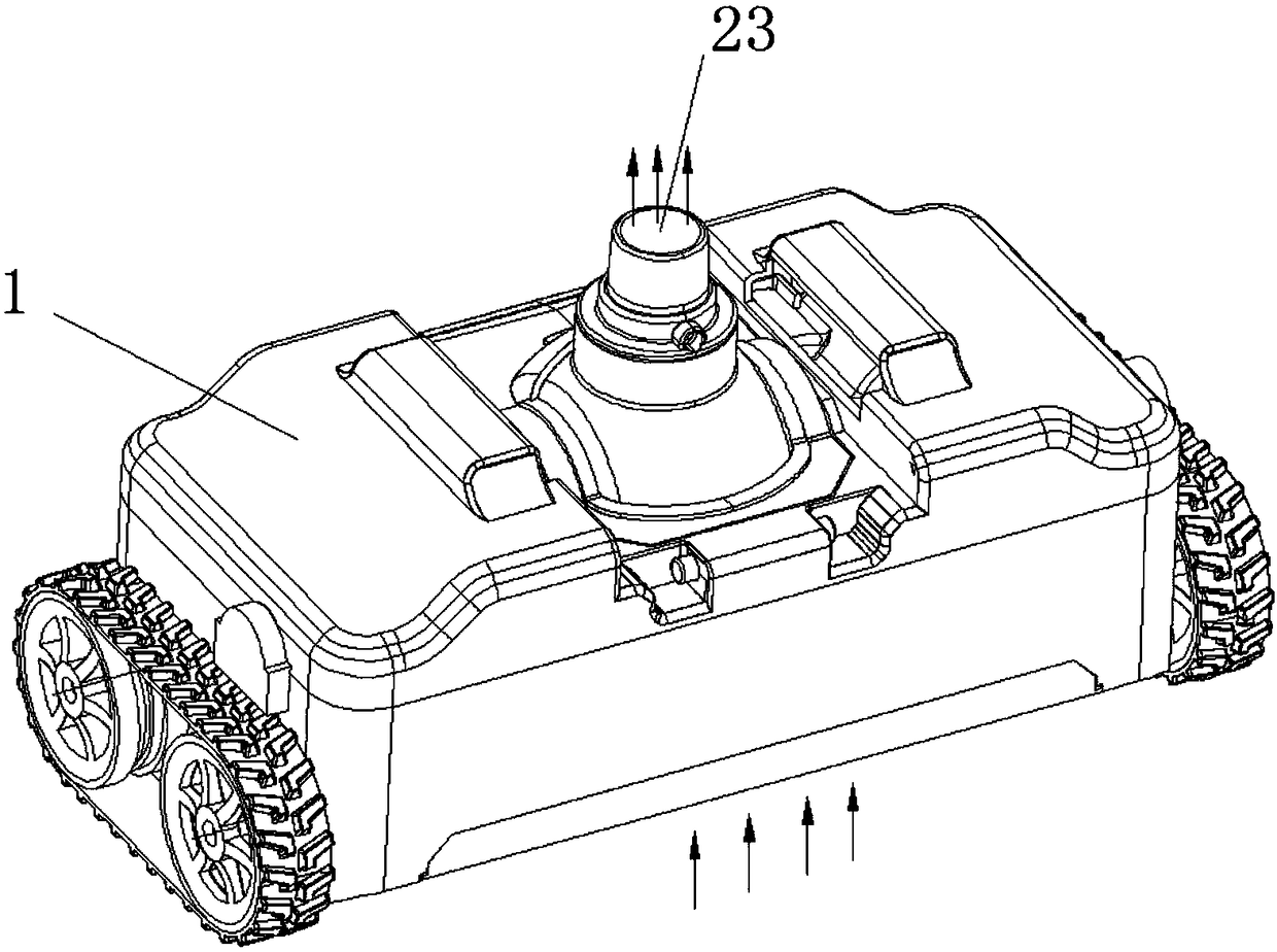
[0043] see Figure 1 to Figure 7 As shown, they are respectively the overall explosion diagram, the overall structure schematic diagram, and the water flow direction of a water energy cleaner of the present invention. figure 1 , indicating the direction of water flow figure 2 , Partial explosion diagram of hydraulic motor fan blade structure, schematic diagram of internal structure of hydraulic motor figure 1 and the internal structure of the hydraulic motor figure 2 .

[0044] like figure 1 and figure 2 As shown, a water energy cleaner includes a fixed housing 1, a hydraulic motor 2, a two-direction switching structure 3 and a power output structure 4, the bottom of the fixed housing 1 is provided with a water suction port 11, and the hydraulic motor 2 is placed in the center of the fixed housing 1, and the two direction switching structures 3 are respectively arranged on both sides of the hydraulic motor 2, and the power output structure 4 is connected to the directi...

Embodiment 2

[0051] As a kind of water energy cleaner as mentioned above, the difference of this embodiment is that, as Figure 9 , Figure 12 and Figure 13 As shown, the direction switching structure 3 includes a gear transmission structure, a switching structure guiding part 31 and a switching structure movable part 32 . The gear transmission structure includes a transmission shaft 331, a reduction gear set 332, a motor output transmission shaft 333 and a power output shaft 334. The transmission shaft 331 is provided with a coaxial sector gear A 3311 and opposite sector gears B 3312 and Sector gear C3313, the reduction gear set 332 is sleeved on the end of the transmission shaft 331, the motor output transmission shaft 333 is meshed with the sector gear A3311, and one end of the power output shaft 334 is placed on the sector gear B 3312 and the sector gear Between C 3313. The switching structure guide 31 is provided with a coaxial gear 311 and a guide groove 312 , and the gear 311 is...

Embodiment 3

[0055] As mentioned above, the difference between this embodiment and Embodiment 1 is that the fan blade 27 is a fan blade 27 whose periphery is made of soft rubber material. During the dirt suction process, there will be garbage cards On the edge of the fan blade 27, but due to the good flexibility of the soft rubber material, the garbage can pass through the inlet channel 24 from the fan blade 27 under the thrust of the water flow, and then be discharged from the water outlet 23. This prevents the fan blade 27 from being stuck by rubbish during operation, thereby affecting the power of the hydraulic motor.

[0056] The baffle 26 is a baffle 26 made of soft rubber. When the fan blade 27 is closed, it passes through the baffle 26 and enters the flow channel sealing cavity. When the fan blade 27 is not closed in place, the fan blade 27 will collide with the edge of the groove of the baffle 26, but because the soft rubber material has good flexibility, it can prevent the fan bla...


PUM


Abstract

The invention provides a water energy cleaner. The cleaner includes a fixed shell, a hydraulic motor, two direction switching structures and a power output structure. The fixed shell is provided witha water suction port, and the two direction switching structures are arranged on the two sides of the hydraulic motor respectively, and a power output structure is connected with a direction switchingstructure. The hydraulic motor includes a flow channel, a motor output shaft, a number of fan blade structures, a number of flow baffles, a water inlet and a water outlet, fan blades are axially fixed on the motor output shaft through a fan blade connection shaft, the fan blades includes a secondary fan blade A and a secondary fan blade B which are overlapped when there is no external force, whensuffering from water flow impact, the secondary fan blade A and the secondary fan blade B open to be perpendicular to the water flow direction, the flow baffles are located on the other side of a cavity, the water inlet is communicated with the water suction, and the water outlet is connected with a water pump. The water energy cleaner achieves sewage suction, walking and reversing functions, hashigher output force stability and larger output torque, and the utilization rate of water energy resources is improved.

Description

technical field [0001] The invention relates to the technical field of swimming pool dirty cleaning equipment, in particular to a water energy cleaner. Background technique [0002] The water energy cleaner is a kind of cleaning equipment for swimming pool cleaning needs. It can crawl independently on the bottom of the swimming pool, go around, repeatedly clean the dirt in the pool, filter the pool water, and make the pool water as clear as new, making it a normal maintenance of the pool. Indispensable device. [0003] Existing many automatic swimming pool cleaning equipments in the prior art. Such as patent CN01237784.8, the name of the utility model is "Automatic Swimming Pool Cleaner", which discloses that a travel motor and a direction motor are arranged on the fixed frame, the travel motor controls the rotation of the travel wheel through the gear connection, and the direction motor controls the direction wheel through the gear connection wheel rotation. [0004] Suc...

Claims


Application Information

Patent Timeline
Patent Type & Authority Applications(China)
IPC IPC(8): E04H4/16
CPCE04H4/1663
Inventor 陈亮
Owner NINGBO POOLSTAR POOL PROD CO LTD
Why Eureka
Try Eureka