
Solar power charger

A technology of solar chargers and solar power panels, which is applied to current collectors, different battery charging, electric vehicles, etc., can solve the problems of not being able to charge, not being able to charge laptops, etc., and achieve low cost, simple structure, and easy to use. Reliable Effect

Inactive Publication Date: 2019-03-05
泰州锦锋光电科技有限公司
View PDF0 Cites 2 Cited by
  • Summary
  • Abstract
  • Description
  • Claims
  • Application Information

AI Technical Summary

Problems solved by technology

[0003] But the existing technology also has many deficiencies. At present, the solar chargers available in the market cannot be charged under weak light, but it is more convenient to charge under visible light (that is, good vision).
Besides, the current solar chargers, charging treasures, etc. can only charge digital products such as mobile phones, and they cannot charge laptops.

Method used


Image

  • Solar power charger
  • Solar power charger
  • Solar power charger

Examples


Embodiment 1

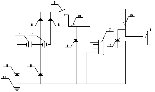
[0019] Embodiment 1: the power output mode conversion module 2, that is, the logic operation mode conversion processing circuit transistor 8 and other semiconductor diodes perform logical operations, so that the output characteristics of the solar power generation panel 1 are changed to:

[0020] 1. When outputting strong light loads, it provides about twice the low-voltage parallel high-current output;

[0021] 2. When the light load is output, it can provide about 2 times of the series power generation voltage, that is, the small current output.

[0022] The electric power that solar power generation panel 1 sends is connected with temperature switch 10 and mobile phone charging output module 7 through function switching switch 9, and temperature switch 10 is protected the working temperature of voltage limiting transistor 11, and voltage limiting transistor 11 is connected in parallel with mobile phone charging output module 7 Between the ground and the ground 14, the outpu...

Embodiment 2

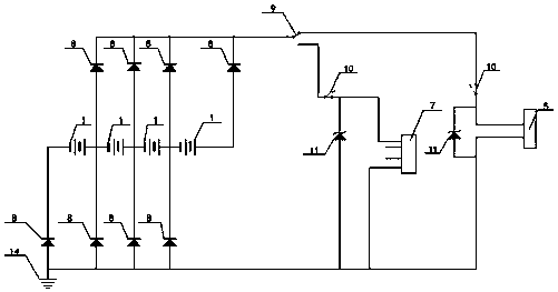
[0026] like image 3 As shown, the power output mode conversion module 2, that is, the logic operation mode conversion processing circuit transistor 8 and other semiconductor diodes perform logic operations, so that the output characteristics of the solar power generation panel 1 are changed to:

[0027] 1. When the light load is output, it provides about 4 times the low-voltage parallel high-current output;

[0028] 2. When the high-voltage load is output, it provides about 4 times the series power generation voltage, that is, the small current output.

[0029] The electric power that solar power generation panel 1 sends is connected with temperature switch 10 and mobile phone charging output module 7 through function switching switch 9, and temperature switch 10 is protected the working temperature of voltage limiting transistor 11, and voltage limiting transistor 11 is connected in parallel with mobile phone charging output module 7 Between the ground and the ground 14, th...


PUM


Abstract

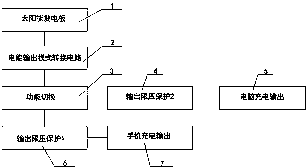
The present invention discloses a solar power charger. The solar power charger comprises a solar power generation board, a power output mode conversion module, a function switching module, a first output voltage limiting protection module, a second output voltage limiting protection module, a mobile phone charging output module, and a computer charging output module. Through the function switchingmodule, the power output mode conversion module is configured to select to form a current loop between the first output voltage limiting protection module and the mobile phone charging output moduleor between the second output voltage limiting protection module and the computer charging output module. Compared with the prior art, by using the solar power charger provided by the present invention, a stable charging current can be better provided for mobile phones, digital electronic products, notebook computers, and the like in a low-light environment that is not directly exposed to sunlight,and the maximum stable generating current can also be provided under strong light.

Description

technical field [0001] The invention relates to a charger, more precisely, a solar charger. Background technique [0002] With the popularity of mobile electronic devices such as mobile phones, electronic digital products, and notebook computers, it has brought a lot of convenience to people's life and entertainment. However, in outdoor, on-the-road and other wild environments, the power consumption of mobile electronic products often occurs. It has brought a lot of troubles to people's entertainment life and work, so it is very necessary to design a portable solar cell phone and a universal charging appliance for computers. [0003] But the existing technology also has many deficiencies. At present, the solar chargers available in the market cannot be charged under weak light, but it is more convenient to charge under visible light (that is, good vision). Besides, current solar chargers, charging treasures, etc. can only charge digital products such as mobile phones, and...

Claims


Application Information

Patent Timeline
IPC IPC(8): H02J7/35H02J7/00H02H7/20
CPCH02J7/0003H02H7/20H02J7/0029H02J7/35
Inventor 高乾寿白林
Owner 泰州锦锋光电科技有限公司
Learn More