Supercharge Your Innovation With Domain-Expert AI Agents!

Wireless local area network communication method and device, access point equipment and station equipment

A wireless local area network and access point device technology, applied in the field of communication networks, can solve the problems of out-of-synchronization between station devices and access point devices, no time synchronization, and inability to completely solve time out-of-synchronization and other problems

Active Publication Date: 2019-03-05
MEIZU TECH CO LTD
View PDF3 Cites 2 Cited by
  • Summary
  • Abstract
  • Description
  • Claims
  • Application Information

AI Technical Summary

Problems solved by technology

[0004] In the related art, a WUR beacon frame (that is, a wake-up beacon frame) is defined, and the frame body part of the WUR beacon frame carries a PTSF (partial time synchronization function, partial time synchronization parameter), which is used to indicate that the secondary communication interface is in In sleep mode, it can maintain time synchronization with the access point. However, because the WUR frame carries some time synchronization information parameters, if the communication device is in sleep mode for a long time, it may not be able to completely solve the problem of time synchronization, and the main communication device of the site device There is no time synchronization in sleep mode, so the longer the sleep mode lasts, the more prone to loss of synchronization between the station device and the access point device

Method used


Image

  • Wireless local area network communication method and device, access point equipment and station equipment
  • Wireless local area network communication method and device, access point equipment and station equipment
  • Wireless local area network communication method and device, access point equipment and station equipment

Examples


Embodiment Construction

[0061] In order to understand the above-mentioned purpose, features and advantages of the present invention more clearly, the present invention will be further described in detail below in conjunction with the accompanying drawings and specific embodiments. It should be noted that, in the case of no conflict, the embodiments of the present application and the features in the embodiments can be combined with each other.

[0062] In the following description, many specific details are set forth in order to fully understand the present invention. However, the present invention can also be implemented in other ways different from those described here. Therefore, the protection scope of the present invention is not limited by the specific details disclosed below. EXAMPLE LIMITATIONS.

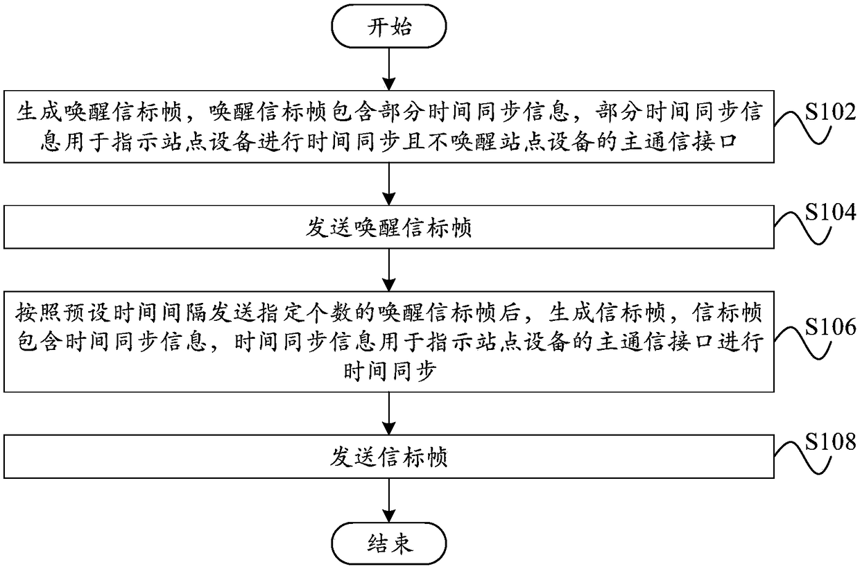
[0063] figure 1 A schematic flowchart of a communication method for a wireless local area network according to an embodiment of the present invention is shown.

[0064] Such as figure 1 As shown, ...


PUM


Abstract

The invention provides a wireless local area network communication method and device, access point equipment and station equipment. The wireless local area network communication method comprises the following steps: generating wake-up beacon frames, wherein the wake-up beacon frames contain partial time synchronization information, and the partial time synchronization information is used for indicating that the station equipment performs time synchronization without waking up a main communication interface of the station equipment; transmitting the wake-up beacon frames; after sending a specified number of wake-up beacon frames according to a preset time interval, generating a beacon frame, wherein the beacon frame includes the time synchronization information, and the time synchronizationinformation is used to indicate that the main communication interface of the station equipment performs time synchronization; and transmitting the beacon frame. According to the technical scheme of the invention, on the premise that the station equipment supports a sleep mode, the probability of time asynchronization between the station equipment and the access point equipment is reduced, and thefrequency spectrum utilization rate and the data throughput are improved.

Description

technical field [0001] The present invention relates to the technical field of communication networks, in particular, to a communication method of a wireless local area network, a communication device of a wireless local area network, an access point device and a station device. Background technique [0002] In July 2016, IEEE (Institute of Electrical and Electronic Engineers, Institute of Electrical and Electronics Engineers) 802.11 established the next-generation Wi-Fi (Wireless Fidelity, Wireless Fidelity) technology research group WUR (Wake up Receiver), namely IEEE (Institute of Electrical and Electronic Engineers, Institute of Electrical and Electronics Engineers) 802.11ba, which is mainly used in the Internet of Things, aims to save power consumption of devices as much as possible. [0003] A wake up frame is defined in the IEEE 802.11ba standard, its main purpose is to wake up the main communication interface of the communication device, that is, the communication de...

Claims


Application Information

Patent Timeline
IPC IPC(8): H04W48/10H04W52/02H04W56/00H04W74/00H04W84/12
CPCH04W48/10H04W52/0225H04W56/00H04W74/002H04W84/12Y02D30/70
Inventor 董贤东
Owner MEIZU TECH CO LTD
Features
  • R&D
  • Intellectual Property
  • Life Sciences
  • Materials
  • Tech Scout
  • Unparalleled Data Quality
  • Higher Quality Content
  • 60% Fewer Hallucinations
Learn More