
Cardiovascular dilation device

An expansion device and cardiovascular technology, applied in the field of medical devices, can solve the problems of blocking blood circulation, loss, convulsions, difficulties, etc., and achieve the effect of stable mechanical support structure and precise and precise control

Inactive Publication Date: 2019-03-08
张檑
View PDF8 Cites 11 Cited by
  • Summary
  • Abstract
  • Description
  • Claims
  • Application Information

AI Technical Summary

Problems solved by technology

[0002] The heart is a hollow muscular organ located in the middle of the thoracic cavity. It is divided into two left and right chambers by a partition. Each chamber is divided into two parts: the upper atrium and the lower ventricle. The atrium collects blood from the heart, and the ventricle ejects The blood flows out of the heart, and there are valves at the inlet and outlet of the ventricle to ensure the one-way flow of blood. The cardiovascular system is composed of the heart and blood vessels, and the blood vessels include arteries, veins and capillaries. A stent or balloon is installed in the patient's cardiovascular system, but because the cardiovascular pipeline is relatively thin, it is difficult to manually install the stent or balloon, and the blood circulation is completely blocked during the expansion process, and the vegetation in the blood vessel cannot be completely removed due to crushing and crushing. Increased work difficulty for medical staff
[0003] In the prior art, the ideal expansion balloon is the Inoue balloon, which has been recognized as superior to any polyethylene balloon for the same purpose, but the Inoue balloon completely blocks the blood circulation during the expansion process, which is likely to cause hypotension, Symptoms such as loss of consciousness and convulsions have added great difficulty to medical staff

Method used


Image

  • Cardiovascular dilation device
  • Cardiovascular dilation device
  • Cardiovascular dilation device

Examples


Embodiment

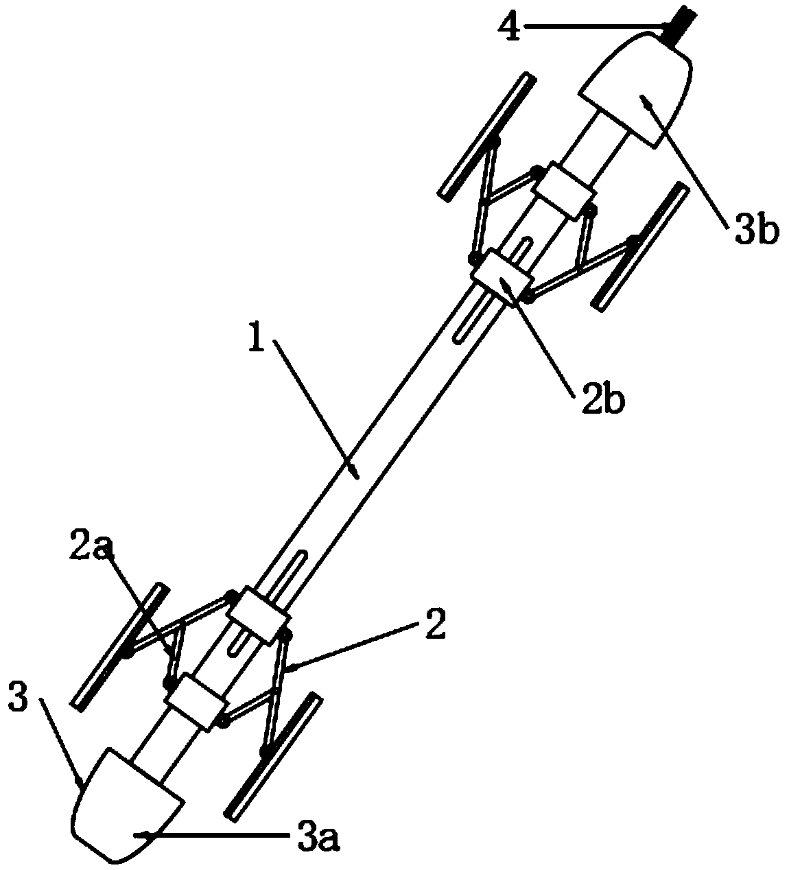
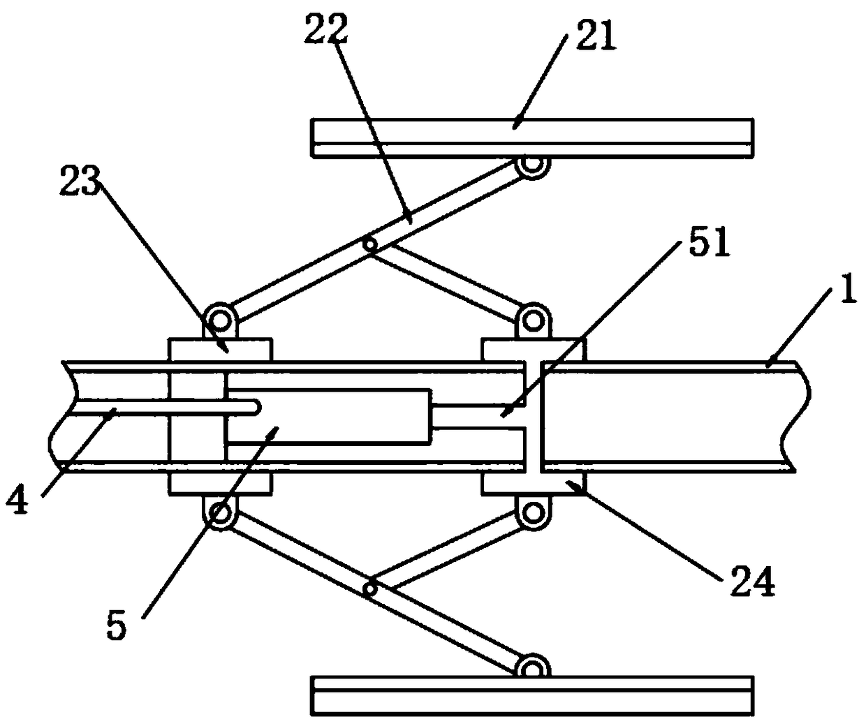
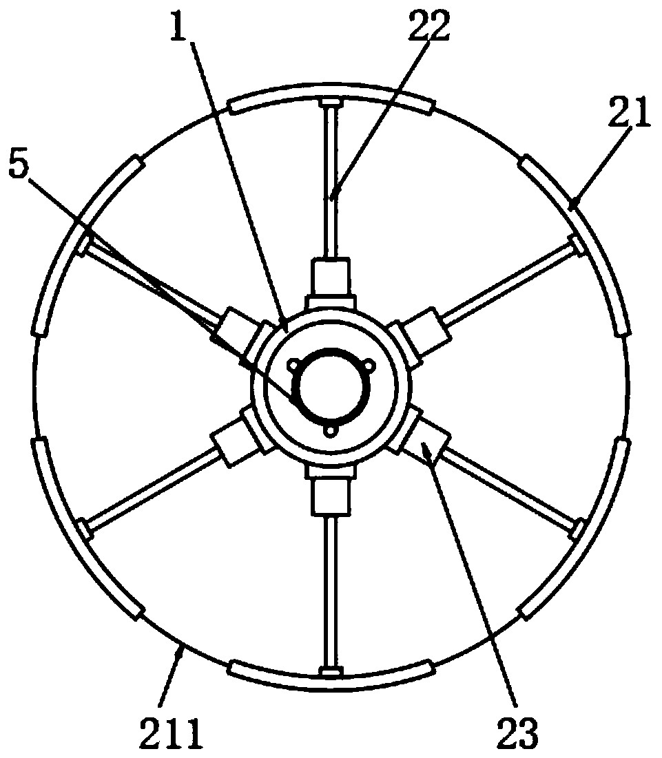
[0021] see Figure 1-4 , the present invention provides a technical solution: a cardiovascular expansion device, including a catheter 1, a dilator 2, an introduction head 3, an air catheter 4 and a compression cylinder 5, the catheter 1 is hollow tubular, and the introduction head 3 is located on both sides of the catheter 1 end, and the introduction head 3 is integrally formed with the catheter 1, the dilator 2 is installed on the outer wall of the catheter 1, close to the inner side of the introduction head 3, and the dilator 2 is fixedly connected with the catheter 1, and the compression cylinder 5 is fixed inside the catheter 1 , close to the expander 2, the output end of the compression cylinder 5 is connected to the expander 2, the air conduit 4 is placed inside the conduit 1, and one end of the air conduit 4 is sealed to the input end of the compression cylinder 5, and the other end is connected to the external air source sealed connection.

[0022] In this embodiment,...


PUM


Abstract

The invention belongs to the technical field of medical instruments and particularly relates to a cardiovascular dilation device. The cardiovascular dilation device comprises a catheter, a dilator, guide heads, an air catheter and a compression cylinder. The catheter in a hollow tube shape and the guide heads at two ends of the catheter are formed integrally, and the dilator is mounted on the outer side wall of the catheter. By arrangement of the dilator formed by a mechanical structure, the compression cylinder drives slide seats of the dilator to slide, and arc supporting faces are supportedby supporting frames through a planar four-rod structure to realize blood vessel supporting while a sufficient gap is reserved to make it convenient for a doctor to dose and clear through the catheter. A driving device in the compression cylinder is provided with a damping guide rod to enable uniform speed and slowness in movement of a piston, an output shaft is driven to move by changing of airpressure, accurate control is realized, high stability of the mechanical supporting structure is achieved, and accordingly surgical smoothness can be guaranteed.

Description

technical field [0001] The invention belongs to the technical field of medical devices, and in particular relates to a cardiovascular expansion device. Background technique [0002] The heart is a hollow muscular organ located in the middle of the thoracic cavity. It is divided into two left and right chambers by a partition. Each chamber is divided into two parts: the upper atrium and the lower ventricle. The atrium collects blood from the heart, and the ventricle ejects The blood flows out of the heart, and there are valves at the inlet and outlet of the ventricle to ensure the one-way flow of blood. The cardiovascular system is composed of the heart and blood vessels, and the blood vessels include arteries, veins and capillaries. A stent or balloon is installed in the patient's cardiovascular system, but because the cardiovascular pipeline is relatively thin, it is difficult to manually install the stent or balloon, and the blood circulation is completely blocked during t...

Claims


Application Information

Patent Timeline
IPC IPC(8): A61M29/00
CPCA61M29/00A61M2210/12A61M2210/005
Inventor 张檑顾明明
Owner 张檑
Learn More