Automatic chamfering mechanism for drill rod

A technology of chamfering mechanism and drill pipe, which is applied in the direction of repairing drilling, drilling tool accessories, boring/drilling, etc., can solve the problems of burrs, time-consuming and laborious, and heating of the grinding mechanism, and achieves the effect of strong practicability.

Inactive Publication Date: 2019-03-08
方陈
View PDF0 Cites 0 Cited by
  • Summary
  • Abstract
  • Description
  • Claims
  • Application Information

AI Technical Summary

Problems solved by technology

[0004] The purpose of the present invention is to provide an automatic chamfering mechanism for drill rods, to solve the problem that burrs will appear near the opening of the plate after the existing drill bit punches a light material (such as a plate), and these When the burrs are removed, it is necessary to grind the burrs on both sides of the plate twice, which is time-consuming and laborious, and the grinding mechanism will also be heated

Method used


Image

  • Automatic chamfering mechanism for drill rod
  • Automatic chamfering mechanism for drill rod
  • Automatic chamfering mechanism for drill rod

Examples


Embodiment

[0027] as attached figure 1 to attach Figure 6 Shown:

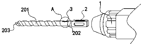
[0028] The present invention provides an automatic chamfering mechanism for drill rods. The automatic chamfering mechanism for drill rods includes a drilling rig 1 and a drill rod 2; one side of the drilling rig 1 is movably connected to a drill rod 2, and the other side of the drill rod 2 is sequentially integrated. There are connection grooves 202, guide rods 201, and cutting heads 203. The inside of the connection groove 202 is riveted with a chamfering mechanism 3, and the outside of the drill pipe 2 is movably connected with a material 4.

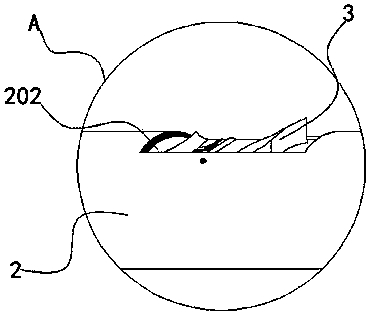
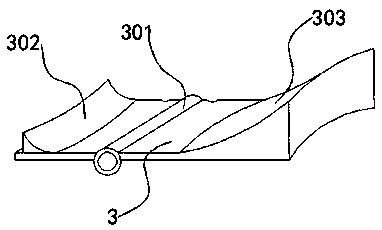
[0029] Among them, as attached figure 2 to attach image 3 As shown: the chamfering mechanism 3 includes a positioning shaft 301, a first convex plate 302, a second convex plate 303, a first diversion groove 3021, and a second diversion groove 3031. The connecting groove 202 is riveted with a positioning shaft 301 inside, The positioning shaft 301 is integrally provided with...


PUM


Abstract

The invention provides an automatic chamfering mechanism for a drill rod. The automatic chamfering mechanism for the drill rod comprises a drill machine and a drill rod, wherein one side of the drillmachine is flexibly connected with the drill rod, and the other side of the drill machine is successively integrated with a connecting groove, a guide rod and a cutting head. A chamfering mechanism isconnected with the inner portion of the connecting groove in a riveting mode; materials are flexibly connected with the outer portion of the drill rod. According to the automatic chamfering mechanismfor the drill rod, when the contact depth between a second convex plate and the materials is increased, due to the side edge of the second convex plate is high and applying the lever principle of a locating shaft is the shaft, a first convex plate is subjected to move outside the connecting groove, and then polishes around a hole on the other side of the materials, making a device in the polishing process improve.

Description

technical field [0001] The invention relates to the technical field of drill bits, in particular to an automatic chamfering mechanism for drill rods. Background technique [0002] A twist drill is a tool that drills a circular hole in a workpiece by rotating it relative to a fixed axis. It is named because the chip flute is helical and looks like a twist. The spiral flute has 2 flutes, 3 flutes or more flutes, but 2 flutes are the most common. The twist drill can be clamped in manual or electric hand-held drilling. Tools or drilling machines, milling machines, lathes and even machining centers. [0003] Based on the above description, and in combination with the equipment in the prior art, it is found that after the existing drill bit punches a light material (such as a plate), there will be burrs near the opening of the plate, and when these burrs are to be removed , it is necessary to grind the burrs on both sides of the plate twice, which is time-consuming and labor-int...

Claims


Application Information

Patent Timeline
Patent Type & Authority Applications(China)
IPC IPC(8): B23B41/00B23B51/08B23Q11/00
CPCB23B41/00B23B51/08B23Q11/005
Inventor 方陈
Owner 方陈
Why Eureka
Try Eureka