Automatic stirring and air blowing anti-bridging device

An automatic stirring and air blowing device technology, applied in the field of silos, can solve the problems of unsmooth discharge, blockage, bridging, etc., and achieve the effect of smooth discharge

Pending Publication Date: 2019-03-08
张家港市繁昌机械有限公司
View PDF0 Cites 1 Cited by
  • Summary
  • Abstract
  • Description
  • Claims
  • Application Information

AI Technical Summary

Problems solved by technology

When the material is a binder, bridging is prone to occur, that is, the discharge is not smooth or blocked

Method used


Image

  • Automatic stirring and air blowing anti-bridging device
  • Automatic stirring and air blowing anti-bridging device

Examples


Embodiment Construction

[0013] The automatic stirring and blowing anti-bridging device of the present invention will be further described in detail through specific examples below.

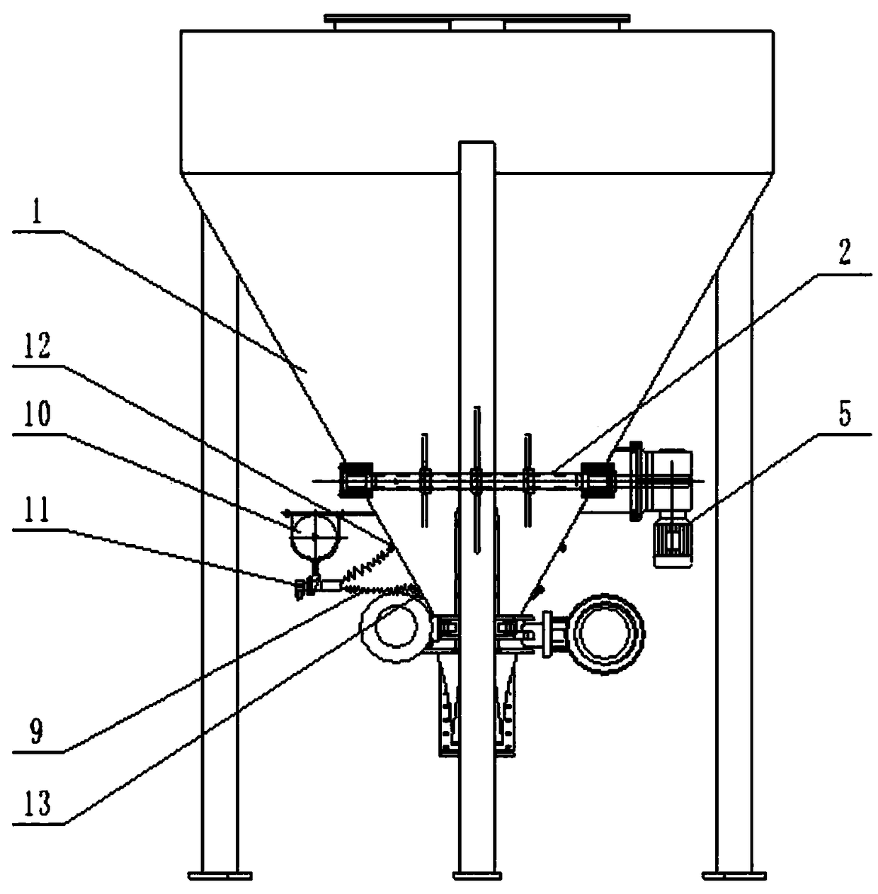
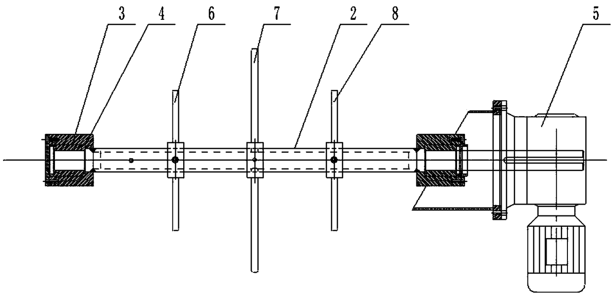
[0014] Such as figure 1 , figure 2 As shown, the automatic stirring and blowing anti-bridging device includes a stirring device and an air blowing device arranged at the bottom of the hopper 1, and the stirring device includes a stirring shaft 2 that is installed in the bottom of the silo 1, and the two ends of the stirring shaft 2 The two ends of the stirring shaft 2 are respectively provided with sealing sleeves 3, and the outside of the sealing sleeve 3 is provided with a positioning sleeve 4, and the positioning sleeve 4 is connected with the feed bin 1. One end of the stirring shaft 2 protrudes from the silo 1 and is connected with the reducer 5. The stirring shaft 2 is arranged horizontally, on which the left paddle 6, the middle paddle 7 and the right paddle 8 are arranged. Since the middle paddle 7 is located ...


PUM


Abstract

The invention relates to an automatic stirring and air blowing anti-bridging device. The device comprises a stirring device and an air blowing device, wherein the stirring device and the air blowing device are arranged at the lower part of a material bin, the stirring device comprises a stirring shaft arranged in the lower part of the material bin in a penetrating mode, the two ends of the stirring shaft are in sealing connection with the material bin, one end of the stirring shaft extends out of the material bin and is connected with a speed reducer, and paddles are arranged on the stirring shaft; and the air blowing device comprises an air pipe joint arranged at the lower part of the material bin, the air pipe joint communicates with the interior of the material bin, and the air pipe joint is connected with an air source through a pipeline. The stirring shaft and the paddles are arranged at the lower part of the material bin of the device, materials can be stirred, so that the materials cannot bond with one another, namely the materials are in a fluffy state; and the air blowing device is additionally arranged, so that the materials move under the action of airflow, the phenomenon of bridging is avoided, and the discharging is smooth.

Description

【Technical field】 [0001] The invention relates to the technical field of silos, in particular to an automatic stirring and air blowing anti-bridging device. 【Background technique】 [0002] The main function of the silo is to store materials, and the materials are discharged from the discharge port at the lower end of the silo and transported to the required equipment by the conveyor. For the convenience of discharge, the lower part of the silo is usually a tapered structure that gradually narrows, and the bottom is the discharge port. When the material is a binder, bridging is prone to occur, that is, the discharge is not smooth or blocked. 【Content of invention】 [0003] In order to solve the above problems, the object of the present invention is to provide an automatic stirring and air blowing anti-bridging device which can make the discharge smooth. [0004] In order to achieve the above object, the technical solution adopted by the present invention is: an automatic ...

Claims


Application Information

Patent Timeline
Patent Type & Authority Applications(China)
IPC IPC(8): B65D90/00B65D88/70
CPCB65D90/00B65D88/70
Inventor 倪玉标
Owner 张家港市繁昌机械有限公司
Why Eureka
Try Eureka